Roff
Well-Known Member
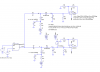
Do you really need to detect that fast damped sinusoid? It requires a wideand amplifier to amplify it. Most wideband amplifiers have high input bias current. If your modulation bandwidth were lower, you could use an op amp with very low bias current.
What information does the modulating signal carry?
What information does the modulating signal carry?
")