Continue to Site

Welcome to our site!

Electro Tech is an online community (with over 170,000 members) who enjoy talking about and building electronic circuits, projects and gadgets. To participate you need to register. Registration is free. Click here to register now.

  • Welcome to our site! Electro Tech is an online community (with over 170,000 members) who enjoy talking about and building electronic circuits, projects and gadgets. To participate you need to register. Registration is free. Click here to register now.

energy detection

Status
Not open for further replies.

jethro107

New Member
hello,
i must to build an energy deterctor using a diode in the square law region. i must to project this circuit using a bat32 diode but it's a month that i try to build it but with no results.
Someone can help me?
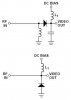
The circuit is very simple, it's composed by a ac voltage generator to 6GHz frequency a diode in serie and a low pass filter at the end. if you kwon a better configuration please answer to this post
thanks
If someone wanto to help me and he need more information please post here the question
in attachement i propose one configuration that i tryied to implement.
 

Attachments

  • Immagine3.JPG
    Immagine3.JPG
    7.3 KB · Views: 177
That circuit should work OK.

Possible problems/queries:
The diode is faulty?
What DC bias are you applying?
Are you sure that the 6Ghz signal generator works OK?
How is the circuit built? On a board with a solid ground plane I hope, NOT on veroboard, breadboard etc.
You mention 6Ghz, try it at a low frequency such as 1 Mhz and when you get good results, try increasing the frequency.

JimB
 
JimB said:
That circuit should work OK.

Possible problems/queries:
The diode is faulty?
What DC bias are you applying?
Are you sure that the 6Ghz signal generator works OK?
How is the circuit built? On a board with a solid ground plane I hope, NOT on veroboard, breadboard etc.
You mention 6Ghz, try it at a low frequency such as 1 Mhz and when you get good results, try increasing the frequency.

JimB
i tried to use these configuration only by the pspice simulator. i applied a 20uA current for bias(as written in literature). i want a detector that work in UWB frequencies range(from 3.1Ghz up to 7 GHz)
thank you for the answer
please help me
 
Roff

He hasn't used any inductors or measured any current!
He has just played with a computer game (simulator).

JimB
 
JimB said:
Roff

He hasn't used any inductors or measured any current!
He has just played with a computer game (simulator).

JimB
I missed that.:eek:
Even with a sim, you need inductor values. A current source in the wrong direction will give some outlandish DC volts, or perhaps the sim won't run.
 
Last edited:
Roff said:
I missed that.:eek:
Even with a sim, you need inductor values. A current source in the wrong direction will give some outlandish DC volts, or perhaps the sim won't run.

this is the cir file that i used
biased detector.cir
*Esempio di curva I-V
.probe
.model BAT62/SIE D(IS=120N RS=200 N=1.04 XTI=1.8 EG=.68
+ CJO=.35P M=.14 VJ=.4 FC=.5 BV=40 IBV=5U TT=25P)

********** INGRESSO **********
V1 1 0 SIN(0 0.01 6G)

********** CAPACITA **********
* SEPARA LA POLARIZZAZIONE *
* DAL SEGNALE APLLICATO IN *
* INGRESSO. *
******************************
C1 1 2 1000p

********** RF CHOKE ***********
* SEPARA L'ALIMENTAZIONE A RF *
* DA QUELLA IN DC *
*******************************
L1 2 4 100n
V2 4 0 0

********** DETECTOR **********
D1 2 3 BAT62/SIE

********** FILTRO PASSABASSO**********
* - LA RESISTENZA FISSA LA BANDA *
* - LA CAPACITà TIENE LA CARICA *
**************************************
C2 3 0 100p
R1 3 0 500


.TRAN 0 1NS
.PLOT TRAN V(1)

.end

in output i find the same signal in input attenuated.
nothing similar to the effect of the square law region
thanks for the answer
 
I cannot really comment on your Spice set-up, I am not familiar with simulators.

What output are you expecting from the circuit?
What you should get is a DC voltage which is in some way proportional to the peak value of the RF input.

JimB
 
jethro107 said:
this is the cir file that i used
biased detector.cir
*Esempio di curva I-V
.probe
.model BAT62/SIE D(IS=120N RS=200 N=1.04 XTI=1.8 EG=.68
+ CJO=.35P M=.14 VJ=.4 FC=.5 BV=40 IBV=5U TT=25P)

********** INGRESSO **********
V1 1 0 SIN(0 0.01 6G)

********** CAPACITA **********
* SEPARA LA POLARIZZAZIONE *
* DAL SEGNALE APLLICATO IN *
* INGRESSO. *
******************************
C1 1 2 1000p

********** RF CHOKE ***********
* SEPARA L'ALIMENTAZIONE A RF *
* DA QUELLA IN DC *
*******************************
L1 2 4 100n
V2 4 0 0

********** DETECTOR **********
D1 2 3 BAT62/SIE

********** FILTRO PASSABASSO**********
* - LA RESISTENZA FISSA LA BANDA *
* - LA CAPACITà TIENE LA CARICA *
**************************************
C2 3 0 100p
R1 3 0 500


.TRAN 0 1NS
.PLOT TRAN V(1)

.end

in output i find the same signal in input attenuated.
nothing similar to the effect of the square law region
thanks for the answer
I ran your sim, but added 20uA bias current through L1, and got about 18uV p-p demodulated output for a 20mV p-p input modulation (basically, carrier off to 20mV p-p carrier on). You had said you used 20uA detector bias, but it does not appear in your netlist. :confused:
I can post the sim a little later. The second half of the Super Bowl is about to start.:D
BTW, 1ns is much too short for the sim time. That's only 6 cycles of the carrier, not nearly enough time to allow the capacitors to settle, etc.
You probably need to run it for at least 10usec.
 
Here ya go.
 

Attachments

  • 6GHz detector sch.PNG
    6GHz detector sch.PNG
    12.1 KB · Views: 155
  • 6GHz detector waves.PNG
    6GHz detector waves.PNG
    15.4 KB · Views: 134
Roff said:
I ran your sim, but added 20uA bias current through L1, and got about 18uV p-p demodulated output for a 20mV p-p input modulation (basically, carrier off to 20mV p-p carrier on). You had said you used 20uA detector bias, but it does not appear in your netlist. :confused:
I can post the sim a little later. The second half of the Super Bowl is about to start.:D
BTW, 1ns is much too short for the sim time. That's only 6 cycles of the carrier, not nearly enough time to allow the capacitors to settle, etc.
You probably need to run it for at least 10usec.

i posted a file without bias current, sorry.
thank you for the simulation result.
can i ask you the value of the bias V1?
thank you
 
jethro107 said:
i posted a file without bias current, sorry.
thank you for the simulation result.
can i ask you the value of the bias V1?
thank you
It's on the schematic, near the bottom of the V1 symbol. One volt.
 
This is good training for using a simulator but what practical purpose this has is beyond me.

At 6GHz every connection is an inductor and capacitor and a simulation package doesn't account for this. If you try building this on veroboard you will fail.
 
Hero999 said:
This is good training for using a simulator but what practical purpose this has is beyond me.

At 6GHz every connection is an inductor and capacitor and a simulation package doesn't account for this. If you try building this on veroboard you will fail.
That's true, but the circuit will actually work in hardware. Like many things, the devil is in the details. I suspect you know all of this, but I'll say it anyway for the benefit of others.
The trick is to build it so you don't add unwanted components (inductors, capacitors) to the circuit. As you said, Veroboard is not the way to do it, but I have breadboard material that consists of a 0.1" grid of plated-through holes, with ground plane surrounding them on one side, and I'm sure you could successfully build it on that. I couldn't test it, because I don't have a 6GHz generator.:( Not to mention that it really doesn't interest me.
 
Roff said:
That's true, but the circuit will actually work in hardware. Like many things, the devil is in the details. I suspect you know all of this, but I'll say it anyway for the benefit of others.
The trick is to build it so you don't add unwanted components (inductors, capacitors) to the circuit. As you said, Veroboard is not the way to do it, but I have breadboard material that consists of a 0.1" grid of plated-through holes, with ground plane surrounding them on one side, and I'm sure you could successfully build it on that. I couldn't test it, because I don't have a 6GHz generator.:( Not to mention that it really doesn't interest me.
thank you roff!!!
I tested the circuit and it work very well also in the reality.
now i have an other problem, i tried to used an amplifier and an ADC but the circuit works very well when i use 1 volt input signal but the i put a 0.1 volt signal the input of the amplifier became negative(it's v(4) in the picture below)
if you can, help me please.
i post the cir file and the simulation output of the 1 volt input signal and 0.1 volt input signal

biased detector.cir
*Esempio di curva I-V
.probe
.model BAT62/SIE D(IS=120N RS=200 N=1.04 XTI=1.8 EG=.68
+ CJO=.35P M=.14 VJ=.4 FC=.5 BV=40 IBV=5U TT=25P)

.inc ./AD8009.cir
.inc ./AD8611.cir

*EXP( {v1} {v2} {trise_delay} {tau_rise} {tfall_delay} {tau_fall) )
*Vname 12 0 PULSE(0V 0.01V 0S 0.5nS 0.5nS 100nS 200nS)
*V1 - initial voltage; V2 - peak voltage; TD - initial delay time; Tr - rise time; Tf - fall time; pwf - pulse-wise; and Period - period.
Vname 12 0 EXP(0V 0.1V 0S 0.5nS 0S 40nS)

Vd 13 0 sin(0 1V 4GHz)
****** INGRESSO **********
Epulse 1 0 VALUE = {V(12)*v(13)}
*V1 1 0 SIN(0 0.7 6G)


********** CAPACITA **********
* SEPARA LA POLARIZZAZIONE *
* DAL SEGNALE APLLICATO IN *
* INGRESSO. *
******************************
C1 1 2 1000pF

********** RF CHOKE ***********
* SEPARA L'ALIMENTAZIONE A RF *
* DA QUELLA IN DC *
*******************************
L1 2 5 33nH
C4 5 0 10nF
R1 5 6 50kOhm
V2 6 0 1V

********** DETECTOR **********
D1 2 3 BAT62/SIE

********** FILTRO PASSABASSO**********
* - LA RESISTENZA FISSA LA BANDA *
* - LA CAPACITà TIENE LA CARICA *
**************************************
C2 3 0 10pF
R2 3 0 500Ohm

R_LPF 3 4 1kOhm
C_LPF 4 0 10pF

******** AMPLIFICATORE AD8009 ********

R21 27 0 10
R20 28 27 1000
R25 28 0 100

Xamp 4 27 100 0 28 AD8009an

VCC 100 0 5V

******** ADC D8611 ******
Xcomp 28 99 100 0 0 0 7 8 ad8611
Rout 7 0 50
Rx 98 99 1k
Vcomp 99 0 1.8V


.TRAN 0 1uS
.PLOT TRAN V(1)

.end
 

Attachments

  • ouput- 0.1 v.JPG
    ouput- 0.1 v.JPG
    154.4 KB · Views: 166
  • ouput- 1 v.JPG
    ouput- 1 v.JPG
    130.3 KB · Views: 153
Jethro, I'm not going to try to decipher your netlist again. Post a schematic, as a .png or a .gif file. JPG schematics are fuzzy.
 
Roff said:
Jethro, I'm not going to try to decipher your netlist again. Post a schematic, as a .png or a .gif file. JPG schematics are fuzzy.
Roff said:
Jethro, I'm not going to try to decipher your netlist again. Post a schematic, as a .png or a .gif file. JPG schematics are fuzzy.
sorry
this is the jpg of the schematic

:)
 

Attachments

  • detector.JPG
    detector.JPG
    34.9 KB · Views: 245
With +5V and 0V power rails, the input common mode range of the AD8009 is 1.2V to 3.8V. Your input signal is below that range.
The detector output is negative because the op amp bias current is 50uA.
You could use a negative supply to solve the common-mode range problem, but the bias current would still be an issue. Since your detector output has no DC information, perhaps you could AC couple it to the amplifier.
Since the AD8009 is a current feedback amplifier, you need to pay attention to the values of the feedback resistors, as well as the package, and not just their ratio. I have designed many video amplifiers using CF amplifiers, and it is not a trivial process. I doubt you can get a gain of 100 out of one stage while maintaining the bandwidth required to handle the detected signal in your example.
Why are you doing this? Is it homework?
 
Roff said:
With +5V and 0V power rails, the input common mode range of the AD8009 is 1.2V to 3.8V. Your input signal is below that range.
The detector output is negative because the op amp bias current is 50uA.
You could use a negative supply to solve the common-mode range problem, but the bias current would still be an issue. Since your detector output has no DC information, perhaps you could AC couple it to the amplifier.
Since the AD8009 is a current feedback amplifier, you need to pay attention to the values of the feedback resistors, as well as the package, and not just their ratio. I have designed many video amplifiers using CF amplifiers, and it is not a trivial process. I doubt you can get a gain of 100 out of one stage while maintaining the bandwidth required to handle the detected signal in your example.
Why are you doing this? Is it homework?
thank you.
it'snt an homework it's a part of my master thesis but i'm not an Electrical engineer(i study informatic and telecomunication and I had only an electronic course for the basis of electronic) and for this, in this phase of my work, i have much problem to build the circuit and my tutor don't find the time for look my problem (he is a ******* if i must to use the right words). i'll try to use multiple stage of amplification
 
Roff said:
With +5V and 0V power rails, the input common mode range of the AD8009 is 1.2V to 3.8V. Your input signal is below that range.
The detector output is negative because the op amp bias current is 50uA.
You could use a negative supply to solve the common-mode range problem, but the bias current would still be an issue. Since your detector output has no DC information, perhaps you could AC couple it to the amplifier.
Since the AD8009 is a current feedback amplifier, you need to pay attention to the values of the feedback resistors, as well as the package, and not just their ratio. I have designed many video amplifiers using CF amplifiers, and it is not a trivial process. I doubt you can get a gain of 100 out of one stage while maintaining the bandwidth required to handle the detected signal in your example.
Why are you doing this? Is it homework?
hi,
i think that one stage amplifier it is the better solution because it coult be problem with the noise. so i think that an amplifier with output over 20-30 mV can be acceptable. i tested this solution but the problem is always the same: negative value of the amplifier input when i connect it to the detector circuit.
i tried to add a negative bias to the amplifier but the solution it's not good.
 
Status
Not open for further replies.

Latest threads

New Articles From Microcontroller Tips

Back
Top