FC-Emulator
New Member
Hi
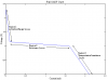
I'm designing an electronic emulator for a (electrochemical) fuel cell. The design must mimic the behaviour of the fuel cell (see attachment). From the curve, the voltage is inversely proportional to current (which does not satisfy Ohm's Law: V is directly proportional to I).
I tried few approaches but can't get to agree with the characteristic curve.
May you kindly offer some ideas of how to approach this design.
Thank you
")