Continue to Site

Welcome to our site!

Electro Tech is an online community (with over 170,000 members) who enjoy talking about and building electronic circuits, projects and gadgets. To participate you need to register. Registration is free. Click here to register now.

  • Welcome to our site! Electro Tech is an online community (with over 170,000 members) who enjoy talking about and building electronic circuits, projects and gadgets. To participate you need to register. Registration is free. Click here to register now.

Emitter follower with different GND potential

Status
Not open for further replies.

treegram

New Member
I am proceeding with my project, and have found the remaining question for me is this:

I have a 20Hz 5Vpp sinewave. The circuit generating it is a PIC with op amp buffer. It runs on a 6V battery supply with the normal ground at 0V.

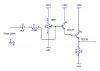
I would like to feed this into a darlington emitter follower that has +12 and +6 rails. In other words, I want the output DC level to be shifted upward 6V from the input. As well as the expected increase in current.

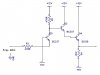
This is the circuit I have breadboarded, but nothing I know to try has worked. Can someone please tell me what needs to be changed to achieve the above result?
 

Attachments

  • emitter_follower.jpg
    emitter_follower.jpg
    30.9 KB · Views: 239
Level shift

You can't quite get there with the darlington since it has 2 Vbe drops the signal can only get to about 10.6 volts not 11.
But if you can live with less here is one that should work.
How much current did you need?
 

Attachments

  • em fol.PNG
    em fol.PNG
    71.8 KB · Views: 162
You will not be able to shift the center of the sinewave up to 6 volts with the lower supply on output being 6 vdc. You need to keep some current flow in the last emitter follower when the sinewave make its negative going excursion.

With 5 vpp, and centered at +6 vdc there would be only 1 volt to ground if the 6 vdc is reduced to ground.

VR1 bias would be about 7.25 vdc. Two diode drops to output puts output emitter quiescent at about 6 vdc. -5 volt excursion to sinewave negative peak takes it to 1 volt above ground.

On positive going sinewave peak you don't have 5 volts of overhead above 7.25 VR1 bias so need to raise 12 vdc a bit.

Keep in mind that input waveform is not symetrical there will be a bias shift based on its DC average.

Wops, I misread 5 vpp as 5 vpk. You have the necessary headroom on VR1 above 7.25 vdc bias with only 2.5 vpk. Just ground output emitter resistor instead of putting it at 6 vdc.
 
Last edited:
Sorry, but I am confused because I do not see both the 0V ground of the 5V input signal and the +6V rail on your schematic. If the ground symbols are meant to represent +6V, where is the 0V signal ground connected? To my limited understanding, all I can see drawn is a normal op amp buffer and emitter follower. The +12 and +6 volt rails are necessary to my application. Can you please clarify?

Current can be 100ma, or whatever is allowed by the transistor rating.
 
Thank you RC. But the present need is for a symmetrical ouput swing between the +12 and +6V rails, so I cannot really ground the emitter. Wouldn' that be too easy ;-)
 
Someone suggested this circuit as one possibility. But it seems incomplete to me. Can anyone here please advise what, if anything is missing? I am determined to get this going ...
 

Attachments

  • translator.jpg
    translator.jpg
    29.9 KB · Views: 166
Someone suggested this circuit as one possibility. But it seems incomplete to me. Can anyone here please advise what, if anything is missing? I am determined to get this going ...

Hi,
This is the output that the circuit gives, not what you are wanting.

Corrected the Vin to 2.5Vpk

EDIT:
Is this closer to the required output.? Note the +15V and +5V supply.
 

Attachments

  • AAesp02.gif
    AAesp02.gif
    27.1 KB · Views: 172
  • AAesp04.gif
    AAesp04.gif
    27.5 KB · Views: 183
Last edited:
Thank you Eric. Yes the input can be attentuated from 5V to 2.5 or whatever works. But I had intended to use three standard 6V batteries, as per the schematic below, for a practical portable device.

Irrespective of the output amplitude, is there any way to make the circuit work on this basis? For example by offsetting the input signal with a pot between the +12 and +6 rails. Any suggestions would be appreciated.
 

Attachments

  • emitter_follower_2.jpg
    emitter_follower_2.jpg
    29.9 KB · Views: 178
Its not possible to get a 12V output from an emitter follower thats powered by 12V.

EDIT:
You could use your 3, 6V batteries this way.
 

Attachments

  • AAesp05.gif
    AAesp05.gif
    30.1 KB · Views: 145
Last edited:
Would have to take R5 and collector of Q3 above 12 vdc, to about 13 vdc to account for two diode drops of two emitter followers and make the required 11.5 v peak on output. VR bias would be about 10.25 vdc to get 9 vdc quiescent on output.
 
Level Shift

I think I might understand.:confused: 
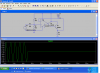
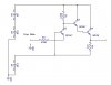
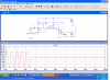
You are interfacing with an existing circuit (the darlington) that is floating on +6 volts. If that is correct the darlington output could never had made it to +12 volts so you may not care if it is clipped. Here is one with the sine wave centered about 9 volts. Is that what you are looking for? If not where do you want the darlington output to be centered and how large must the voltage swing be?
 

Attachments

  • lvl.PNG
    lvl.PNG
    72.8 KB · Views: 156
Thanks to everyone for the most recent replies. When I mentioned the output "swing between +6 and +12V", I meant centered between these (on 9V), at the greatest practical amplitude, not necessarily rail-to-rail. I understand the darlington's voltage drop.

All of the circuits provided are very useful, and I have printed out copies for future reference. Ron's latest op amp design is spot on though. I will just need to center the output swing to avoid clipping. Hopefully, it will all work out on the bench today.

To complete the intent of my original post, I also need to make a matching separate circuit that uses -6V and -12V rails. The upper rail is still more positive, and the potential is the same, so I assume it's just a matter of changing the rails accordingly.
 
I hope I am not overstaying my welcome with this somewhat eccentric project. Attached is my latest effort, based upon the circuit Ron kindly provided. Still no success though, due to my own inexperience. Can anyone please advise where the problem is?

The point of the exercise was to have the output swing symmetrically between the +12V and +6 volt battery terminals, with no reference to a common ground. This is physically different from floating the potential somewhere above ground.

Is this really as hard as it seems?
 

Attachments

  • opto_translator.jpg
    opto_translator.jpg
    37.1 KB · Views: 148
hi treegram,
Whats wrong with the circuit in post #9.?:rolleyes:
It works from 3 off, 6V batteries and does exactly what you are asking, its based on your original circuit,???
 

Attachments

  • AAesp02.gif
    AAesp02.gif
    39 KB · Views: 170
As far as I can tell, the circuit Eric has generously provided outputs a sinewave of 12V amplitude that is shifted 6V upward from the low side of a 0-18V supply. However, this is is not what I am attempting to describe. Please allow me to explain.

Here is an analogy using audio components. A 2V 440Hz sinewave is fed into a 12V amplifier (a 10W kit type) via a 1:1 coupling transformer. So there is no ground reference between the two.

The amplifier is powered from +24V and +12 rails (with no ground), providing the specified potential of +12V. Please refer to attached diagram.

These voltages are provided by two 12V SLA's in series, and a third connected in parallel between their +24V and most negative terminal. The + rail is taken from the +24 terminal of the 2 batteries in series. The "-" rail is taken from the +12V terminal of the battery in parallel.

In relative terms, the resulting signal will look the same as in Eric's spice sim. And, of course, he is correct in pointing this out. But in terms of absolute charge distribution, the two are different. This is what I hope to objectify with my forthcoming experiment.

One further point. Since the negative side of the two batteries in series and the one in parallel are linked, the latter will tend to be charged. This is an unwanted side-effect of this configuration, but I have found no way around it while keeping with the intent. Unless someone can offer better advice, I suppose I will have to rotate the batteries periodically to avoid damage.
 

Attachments

  • +24_+12_amp.jpg
    +24_+12_amp.jpg
    24.5 KB · Views: 138
Since we have no ground what is the point of reference for the output. In other words. The scope is floating, the probe is one the output. Where is the "ground" lead for the scope?
 
Yes, there is no common between the signal input and amp. The kit amp module will have two output pins though, one connected to the neutral rail. The latter could be used, or perhaps the link between the two negative battery terminals. I will be away for a few weeks now, When I return, I will shell out for some more parts and see what happens on the bench. Thanks again for your most generous assistance.
 
Status
Not open for further replies.

Latest threads

New Articles From Microcontroller Tips

Back
Top