donperry
New Member
Good day guys,
I'm building an arduino based water injection controller for motor vehicle. It Uses the Airflow sensor and manifold pressure sensors as input. On my test bench the device works fine, doesn't hang and could go on for hours.
In the car, on ignition only (car not running) the device works fine. However, once the car is running it freezes after a few seconds/ minutes, just randomly whenever it feels like.
I opened up the pressure trace (to disconnect from circuit) and the device still hanged.
I opened up the Air flow trace and then the problem goes away.
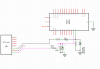
The pink line is the MAF line, the other is pressure
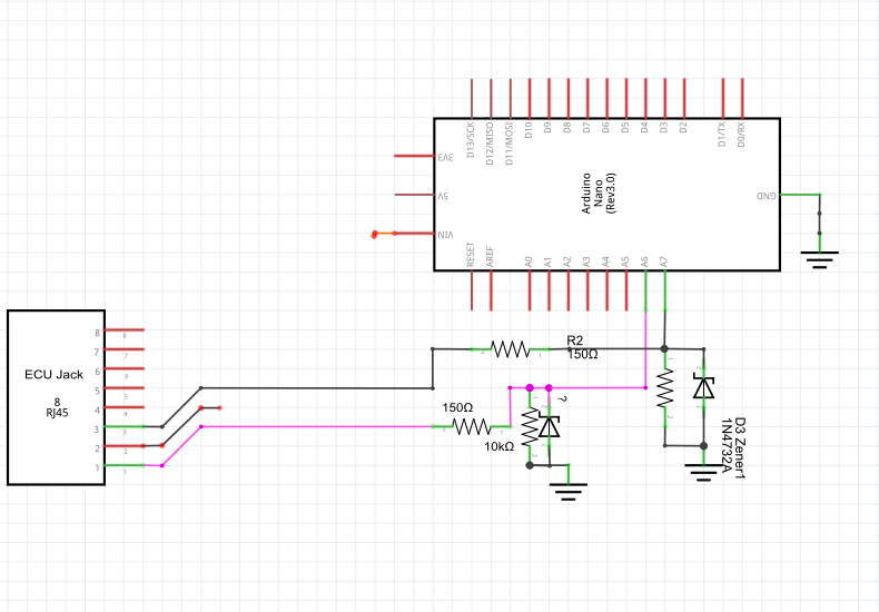
So now I'm thinking the MAF (air flow ) sensor input is causing this. I'm suspecting some noise or spikes or something is causing this. What approach would be best in keeping things stable here?
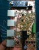
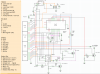
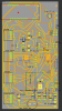
I have attached complete and partial schematic, PCB print, and actual device
I'm building an arduino based water injection controller for motor vehicle. It Uses the Airflow sensor and manifold pressure sensors as input. On my test bench the device works fine, doesn't hang and could go on for hours.
In the car, on ignition only (car not running) the device works fine. However, once the car is running it freezes after a few seconds/ minutes, just randomly whenever it feels like.
I opened up the pressure trace (to disconnect from circuit) and the device still hanged.
I opened up the Air flow trace and then the problem goes away.
The pink line is the MAF line, the other is pressure
So now I'm thinking the MAF (air flow ) sensor input is causing this. I'm suspecting some noise or spikes or something is causing this. What approach would be best in keeping things stable here?
I have attached complete and partial schematic, PCB print, and actual device
 but if I have the symbols I might try and give it a go later.