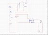
Hi i'm very new to electronics and still trying to learn. In order to save time and money I thought I'd use electronics workbench to try out some simple circuits and see if they work. I'm getting weird results tho from simple circuits that seem to run fine till I flip a few switches in the design then I get errors like trouble with node $15 yet I can't see how there is any errors. Would one of you be so kind as to take a look at this and see what i've done wrong?
Continue to Site