Continue to Site

Welcome to our site!

Electro Tech is an online community (with over 170,000 members) who enjoy talking about and building electronic circuits, projects and gadgets. To participate you need to register. Registration is free. Click here to register now.

  • Welcome to our site! Electro Tech is an online community (with over 170,000 members) who enjoy talking about and building electronic circuits, projects and gadgets. To participate you need to register. Registration is free. Click here to register now.

Electronics Project " Soil moisture Monitor"

Status
Not open for further replies.

James Ngai

New Member
Dear All,
I'm a newbie in using LT spice IV but i have to learn how to use it within two days which is kind of tough for me, Can anyone tell me what I have done wrong when I pressed the button run , and try to simulate, and the CODE" unknown subcircuit called in .... pops out

This is my file

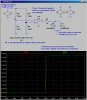
My project needs to develop a simple soil moisture monitor, and I need to insert the probes into the soil and by waiting the soil to dry " the resistance will get higher.. then
The circuit works by using two potential divider circuits , and using the Op amp as a comparator, by comparing two potential dividers the signal will tell you YES or NO to determine dryness.
But did anyone know how could I use LT spice to replace the resistance of a plant?
For now, I'm using a variable resistor to replace the Soil" I can't find SOIL in the LT spice.
Or is it just simply not existent?

Thanks for every one helping me!
 

Attachments

  • project 1.asc
    2.3 KB · Views: 159
Welcome, James,

Here is simulatable circuit. I am showing you how to vary a resistor during simulation. I assuming that you know how the resistance changes as a function of soil moisture. LTSpice is an electronic simulator; it knows nothing about soil conductivity :confused:

The error message came from that fact that you placed an "opamp2" symbol on your schematic, but didn't tell LTSpice what real component that symbol represents. Since I didn't know either, I pointed the symbol at a "generic, parametric" opamp that LTSpice happens to have in its library. It is called "UniversalOpAmp2"; and is a pretty good opamp; much, much better than a 741, for example.

I fixed about three other errors that would have prevented the sim from doing anything useful along the way.

Study and simulate the fixed circuit. I'm sure you will have more questions...

btw-you will likely need to add a little hysteresis to the comparitor to keep it bouncing between two states as the bridge balances.
You might want to add some dead band in middle, where both LEDs light, effectively having the circuit report "too dry", "OK", and "too wet". That would need a second comparitor...
 

Attachments

  • project1a.asc
    2.6 KB · Views: 133
  • Project1a.jpg
    Project1a.jpg
    140.5 KB · Views: 164
Last edited:
Hi Mike,
Thanks a lot ! your suggestion is very helpful!;)
I'm actually a Theoretical physics undergraduate, this is the first time i'm doing electronics , but my demonstrator didn't know how to do it either... :eek:
Our project is actually using a Op amp 741 but i couldn't find it in the LT spice. Your simulation looks really great and I have tried playing around the circuit.
My technician suggested me to add a inverting loop and also a capacitor for absorbing the frequencies to the circuit.

For the resistance of the soil against moisture I would expect to see an exponential decay of resistance as the soil gets saturated with water , is it right?

I'm not too sure what dead band or hysteresis means , but what i did to the circuit is by using a Blue LED with 3.5 V forward voltage, and Red LED with 2.7 V forward voltage

The transition between the light will be gone because the forward voltage is large in opposite direction. I don't see why we want to see the intermediate LIGHT , instead of just Yes and NO? I thought it's better to make only one of the light remain lit

Thanks for your help again!
Cheers!
 
**broken link removed**: Pan down the page to DIY Do It Yourself Sensors.

A 741 is a terrible, obsolete OpAmp. There are thousands of more modern opamps with better specs. For your project, you could use an LM358, which can work well as a comparator on a single low voltage, like a 9V Alkaline battery.
 
Status
Not open for further replies.

Latest threads

New Articles From Microcontroller Tips

Back
Top