Continue to Site

Welcome to our site!

Electro Tech is an online community (with over 170,000 members) who enjoy talking about and building electronic circuits, projects and gadgets. To participate you need to register. Registration is free. Click here to register now.

  • Welcome to our site! Electro Tech is an online community (with over 170,000 members) who enjoy talking about and building electronic circuits, projects and gadgets. To participate you need to register. Registration is free. Click here to register now.

Electronics Help

Status
Not open for further replies.

Tariqp

New Member
I am a product designer and have a project on machine that requires a countdown timer relay when triggered by a start button as well as a wired separate lcd/led display. The timer is set to countdown from 30 seconds.
Can someone build one for me or advise me what components to use and how ?
Thanks
 
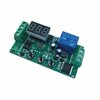
There are a variety of timer modules available on ebay.

This is one of the "more finished" versions. Others are a pcb with a 7-segment LED display.


Screenshot_20210228-183444_Edge.jpg
 
Your requirements are not at all clear. Please describe the functions that you need.
Number of buttons
Type of display
What is displayed
All fixed and adjustable parameters
What does the timer show or not show when operating
What does the timer control

ak
 
Sorry for the lack of info chaps.
I am building a simple machine that is 240V.
The user presses the start button which switches on lights and a fan for 30 seconds and then turns off back in a ready state. I want a simple countdown display that shows the countdown from 30 to 0. I do not want any programming buttons at all. The start and stop buttons are seperate. There is also an in line micro switch for safety.

Hope this helps and thanks for your support.
 
Much better. You described the Start button. What does the Stop button do?

ak
 
Its for if the user would like to stop the countdown completely. kind of like an emergency stop. The unit should then go back to ready if that makes sense.
 
Ive searched the web for something off the shelf and there are plenty of cheap boards that have everything I need built in. The problem is thought the displays are always attached to the boards or the displays have buttons for programming times which is not what I want.
 
Come on guys, play nicely, enough of the squabbling.

JimB
One of the moderators.
 
Language barriers again.... Macintosh obviously thought he was after a freebee..

There are many that will help... There are many "programable " relay boards, but I bet only a few, if any, have your exact requirements.
It would be perfect for a small micro... But it would appear that you don't want that route..
 
As Ian Rogers said i just dont understand exactly. Thats my failing.
I though you wanna design electronics product (schematic, board layout, pcb) free
sorry then, my bad
 
The traditional approach is a clock source - to two BCD presettable up/down counters - to two display decoder/drivers - to two 7-segment LED displays.

The clock source can be a simple 1-gate oscillator that you adjust to get close to 1 Hz, or something derived from a crystal or the powerline.

The counters are hard wired in the down-count mode, with "30" hard-wired into the preset inputs. Note that if the initial display is "30", and changes to "29 one second after the button is pressed (which is what most people expect), then "00" is the 31st count. Just sayin ...

Depending on how large/bright you want the display to be, a CMOS decoder-driver might not be able to supply enough current. In that case, you separate the decoding and driving functions into two chips for each digit.

You also need a couple of gates for the control functions.

Looks like 5 chips minimum, 9 max., plus the two digit display.

An alternative is a small microcontroller - to a 2-digit display driver peripheral chip - to two 7-segment LED displays. Fewer parts, lower cost, more complex, firmware development and debugging ...

OR - a microcontroller with at least 9 I/O pins - to two 7-segment LED displays.

OR - back to a small microcontroller - to a small LCD display with a serial interface.

Or or or ...

What power sources are available?
How big/bright are the displays?
Is the system every going to run on batteries?
Outdoors / harsh / rugged environment?

ak
 
Last edited:
The traditional approach is a clock source - to two BCD presettable up/down counters - to two display decoder/drivers - to two 7-segment LED displays.

The clock source can be a simple 1-gate oscillator that you adjust to get close to 1 Hz, or something derived from a crystal or the powerline.

The counters are hard wired in the down-count mode, with "30" hard-wired into the preset inputs. Note that if the initial display is "30", and changes to "29 one second after the button is pressed (which is what most people expect), then "00" is the 31st count. Just sayin ...

Depending on how large/bright you want the display to be, a CMOS decoder-driver might not be able to supply enough current. In that case, you separate the decoding and driving functions into two chips for each digit.

You also need a couple of gates for the control functions.

Looks like 5 chips minimum, 9 max., plus the two digit display.

An alternative is microcontroller - to a 2-digit display driver peripheral chip - to two 7-segment LED displays. Fewer parts, lower cost, more complex, firmware development and debugging ...

What power sources are available?
How big/bright are the displays?
Is the system every going to run on batteries?
Outdoors / harsh / rugged environment?

ak

Thanks for the reponse, Ive been looking into ardrino's but they look much like a hobbyist rather than a commercial solution.

Power source s are 240v and 24v
I dont have a display as yet but the brightness isn't important aslong as its readable.
I would like the timing device to retain the settings other than that the unit is 13a plug in.
Its an indoor device.

Thanks

T
 
Power sources: AC or DC - ? <it matters>

" the unit is 13a plug in. " -- ?

Packaging - a small box enclosure on a table, wall-mounted on a factory floor, other?

Readable at what distance?

There are a **lot** of microcontroller (uC) boards out there, PIC based, Teensy, etc. If you already have uC firmware within your skill set, that opens up a lot of options.

ak
 
Last edited:
Hi AG, In the UK a 13 A (Amp) plug is the most common plug/socket type. The plug is fitted with a cartridge fuse which can be 13 A, 10 A, 7A. 5A, 3A, 2A to suit the item that is being powered. The sockets are normally wired in the form of a ring main that starts and ends at the output of the circuit breaker which is normally rated at 32 amps. The cable used is normally has 2.5 square mm conductors. (So the conductor diameter would be about 1.8mm)

Les.
 
AK

The power source is AC but has a 24DC supply also.

Its a mobile unit and the timer will be at 5ft eye level. Users will be stood in close proximity to the unit.

Sorry no firmware knowledge.

Thanks

TP

This little fella would do the job but the LCD isn't detachable.
 

Attachments

  • s-l500.jpg
    s-l500.jpg
    20.1 KB · Views: 324
How far away from the PCB does the LED display need to be ? Would it not be possible to unsolder the display and extend it to where you require it ? As it is probably a multiplexed display there would probable need to be 10 or 11 wires (Depending on if the decimal point was used.) Is this a one off machine or a large production run ?

Les.
 
Status
Not open for further replies.

Latest threads

New Articles From Microcontroller Tips

Back
Top