Continue to Site

Welcome to our site!

Electro Tech is an online community (with over 170,000 members) who enjoy talking about and building electronic circuits, projects and gadgets. To participate you need to register. Registration is free. Click here to register now.

  • Welcome to our site! Electro Tech is an online community (with over 170,000 members) who enjoy talking about and building electronic circuits, projects and gadgets. To participate you need to register. Registration is free. Click here to register now.

Electronic fan controller help

Status
Not open for further replies.

srynznfyra

New Member
Hi

I'm building (well, designing at this stage) a simple fan controller to switch one or more fans between either a 12V or 7V supply (using +12V, +5V and ground to achieve the different voltages). This of course makes use of the fact that if you connect something to 12V and 5V, it will receive an effective (12 - 5)V, as the 5V 'pushes back'.

Each fan will have its own toggle switch between 12V, 7V and off, but there will also be a 'turbo' SPST toggle switch to turn all fans up to 12V. The fans are part of my PC's cooling system, and the point of the turbo switch is so that I can quickly turn all fans to the max if the PC is overheating, or if I'm leaving it for a while doing some heavy work (heh, noise doesn't matter while I'm not in the room). I'd also connect a thermistor in parallel with the turbo switch, so if it does overheat it will automatically turn the fans up.

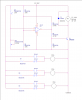
The difficulty I'm having is that I'm trying to accomplish all this using a transistor for each fan; to be precise, an NPN transistor. Here's the schematic:

**broken link removed**

Basically the principle I'm using here, and it might be totally wrong, is that I'm connecting the turbo switch to the base of each transistor (in parallel obviously). Each fan's negative is connected to its respective transistor's collector in parallel with a SPDT switch, however before the switch is a resistor (we'll come to that). The SPDT switches between 5V and 0V for the fan's ground, for an effective voltage of 7V and 12V (respectively) going through the fan. This means that assuming the transistor is OFF, you can manually switch the fan between 12 and 7V (ie. loud/quiet).
Now is where it gets tricky: the transistor's emitter is connected straight to ground. Does this mean that when the transistor is ON, all the electricity going through the fan will go through the transistor (and to 0V for an effective 12V/loud)? Or will there be current leakage through the resistor and (assuming it is switched to 7V) to the +5V supply?

I guess I'm sort of combining a 1-input AND gate with a 1-input NAND/NOT gate using a single NPN, so I wouldn't be surprised if this wreaks havoc ;)

Thanks alot, and I hope you understood my long-winded explanation, although the diagram should help (lol).

Cheers
 
What you are getting at with the 7 volts is if I make 5 volts the common (-) and connect the positive (+) to 12 volts I get 7 volts, the delta between 5 and 12 with ref to 5. This is not going to work in your circuit. All of your transistor emitters are tied to common. There are other errors also.

If you want to do something like this it can be done using a resistor in series with one fan drive and straight 12 volts sans resistor for the other fan drive.

How about you explain in detail what exactly your objective is. Then things can be worked from there.

Ron

Hi, thanks for the reply.

Well, the original problem is that the fans are too loud and powerful on 12V while the PC isn't on full load. So, I thought of the 7V mod. However I want to be able to switch fans to 12V on-demand, so therefore had the idea to make a controller with switches.

The reason each transistor is connected to 0V is because the idea is for the fans to be on full (12V) while the transistor is on, as the transistor is powered when the turbo switch is on (or when the thermistor is hot).

So basically, most of the time (ie. when turbo mode is off), the transistors will be off, and the SPDT switches will decide whether the fans are on 12V or 7V.
 
I'll look at it more when I get home from work today. Maybe we can simplify things a little.

Ron
 
OK, something I noticed and you may want a second opinion is Your transistors will not be on or off (driven into saturation or not). As temperatures change the base current will change but slowly. While I did not look up the 2N3704 that would be my guess.

Given a choice I would use a circuit similar to the attached. Actually really thinking about it I would use a comparator like the LM339 and 4 thermistors. Regardless, the merit to using a comparator in there is ON or OFF with some hysteresis added. In the posted circuit even an old 741 op amp would work fro the comparator portion. I used a 3 pole double throw relay for hi and low speed. The resistors on the relay contacts would be chosen for low fan speed.

Someone else may have some thoughts. Other than you can buy PC Fan Speed Controllers pretty cheap. :)

Ron
 

Attachments

  • Thermistor CKT.png
    Thermistor CKT.png
    27.4 KB · Views: 143
Wow, thanks for that, it now all makes (kinda) perfect sense :D
I think my original mistake was trying to get it to switch between different voltages before and after the load, rather than just put a resistor in series (which is of course the most obvious way of reducing voltage :rolleyes:)

One question though, one of the original goals was to have control over each fan (well, two-speed control anyway). I guess it would be pretty easy to do this, simply put a double throw switch before each limiting resistor leading to either the resistor, or straight to the fan.

Oh yeah, for the jet-engine mode switch (turn all fans to 12V), would the easiest way be to just stick an SPST switch across the collector and emitter of the transistor? This seems the most obvious, but I don't know whether it would be more efficient to do some jiggery-pokery with the op amp (say, put a switch + 15K resistor in parallel with the thermistor maybe).

Btw (I should have mentioned this) the parts referenced in the original circuit were just random parts that I picked in eagle, I didn't actually check their ratings, lol. I just picked them because they were, say, an NPN transistor.

As for the off-the-shelf fan controllers, I was considering that, but I'd have more fun building it myself. More flexible too of course.
 
In my example, just place a simple SPST switch across the thermistor. That would force the op amp to toggle high and turn on the transistor.

The way it works is as the thermistor gets warm its resistance decreases. That causes the voltage to slowly increase at the junction of the thermistor and the adjustment pot (think sensitivity). When that voltage exceeds about 6 volts (the ref set with the two 10K resistors) the op amp toggles high. So if we bypass the thermistor it will toggle high and turn on the transistor which turns on the relay. Now if you like switches then SPST switches could be placed across the resistors in series with the relay contacts. :)

Then you could run any fan (individually) on high at any given time.

Ron
 
Hmm, yeah I didn't really know anything about op amps but I looked them up and they seem pretty simple in terms of concept, a bit like a transistor switch I suppose, except it amplifies the difference between two signals.

Either way, I think I pretty much understand the circuit. The variable resistor is there to set the sensitivity of the thermistor, right? So if it's on low resistance, more current will go from the thermistor to ground and therefore a higher temp would be required to turn on the op amp; conversely if the variable resistor was on high resistance more electrons will flow to the op amp and therefore not such a high temp would be required to turn it on. At least that's the way I see it.
 
You may want to give this link a read with a focus on "Comparator Operation". You see it pretty much as it is. :)

You will see some good examples of using comparators.

Ron
 
I did something similiar for a fan on my aquarium hood, 5v at night and 8v during the lights on period. I used a photodiode and a 741 opmap to toggle a relay. the relay controlled a resistor array to a LM317 adjustable voltage regulator. With the relay open the resistor arrangment to the regulator supplied 5v, when closed it added another resistor in parallel and the voltage increased to 8v.
 
Last edited:
Interesting, sounds pretty much the same as what I'm doing (apart from the voltage regulator). BTW, I've now modded the design to have the relay's NCs connected through adjustable variable resistors (with knobs sticking out the back of the PC), and of course the NOs (turbo mode) straight to the fans without anything in between (so as to supply 12V when needed). Might put a little resistor in there though, or maybe have tiny surface mount switches / DIL switches to enable 'soft' turbo mode on certain fans, say, 9-10V instead of 12 (without rubber attaching thingies the whole case resonates due to the combined vibes produced by all the fans on 12V - it really is LOUD). Some of the fans are louder than others and in more aerodynamically advantageous positions, so it would be cool to be able to individually decide which fans got soft turbo and which ones received the full whack at high temps. I also of course added the obligatory turbo LED to the design (simply a bright blue 3.6V LED+resistor in parallel with the relay coil).

Quick question: the idea is to power all this using a single four pin molex plug from the PSU. These are all 18AWG on my PSU. According to relevant sources, 18AWG can take 2.3A MAX (!). All the fans are connected in (duh) parallel, so I was thinking, the amps going through that poor 18AWG could theoretically get pretty high. I haven't looked/tested all my fans, but the one that's loudest on 12V specifies 0.23A. So to be safe let's say that on turbo mode the four fans together take an amp. So the whole fan controller unit would be that plus the relay coil, plus a small amount used by the resistors and electronics. 1.5A should cover it. I looked up some HDD figures, and it can apparently take 2.5A to spin up a hard drive! This makes me think that 1.5A max (albeit, continuous when it does happen) should be a walk in the park for the PSU and the thickness of its wires, however if you know more about this than me, tell me if you think something bad could happen (I /really/ don't want a third dead(ly) PSU on my hands :p)

Another idea for the future: I was thinking that I could have a bi-colour LED (red/yellow maybe) for each fan. It would stay yellow while temp was low, but the brightness would increase/decrease with the variable resistor. Then, if turbo kicked in it would turn red. I think it would be pretty cool but not necessary, all I really need is an LED telling me that turbo mode is on (which is easy as stated). Implementing the bi colour LEDs would probably require some major re-working of the circuit, so I'll leave it on low priority for now, and maybe actually build the damn prototype!
 
As to the AWG 18 wire gauge used pretty much on all home computer power supplies. The ampacity of any wire is based on a host of variables. "As you might guess, the rated ampacities are just a rule of thumb. In careful engineering the voltage drop, insulation temperature limit, thickness, thermal conductivity, and air convection and temperature should all be taken into account". The 2.5 amps mentioned isn't quite true based on your application. That number for AWG 18 wire is based on "The Maximum Amps for Power Transmission" which uses the 700 circular mils per amp rule, which is very very conservative. What you have is plain chassis wiring which is far from transmission rules. For what it is worth the connector pins and sockets are rated for 5 to 7 amps on a standard 4 pin Molex connector as we like to refer to them. Overall I doubt ampacity will be an issue with your project.

Most home computer fans I have worked with and experimented with (80mm and 120mm) average between 160 and 250 mA when powered from 12 volts. You would be hard pressed to get 4 fans to draw an amp. Your numbers are also pretty much right on for the HDD, my experiences show about 1.5 amps at spin up and less than an amp running. Many did not peak at an amp at spin up.

Again, if you want to be cool about this you could use 4 thermistors with an LM339 comparator. That would give you 4 comparators in a single chip. The merit here is the individual fans could be controlled.

Years ago I did some experiments as to fan speed, what remains of that little science experiment can be seen here. I also did a few experiments on case temperatures and the results (images only) of that little science experiment can be found here. :)

The used ampacity quotes and references can be found here. However, all such tables are about the same.

Ron
 
Last edited:
Thanks for the info about wire current capacity, that's one less thing to have to think about.

Another idea though was to have just one thermistor, but two op amps, relays, thermistor-adjust potentiometers and sets of relevant resistors. The two intake fans would be on one relay, and the two exhaust ones on the other. This way I could have the exhaust turbo mode more temp-sensitive than the intake, reasoning that negative pressure is better for getting rid of hot pockets of air if the temps are high. Although, this would probably make the intake op-amp/relay circuit a bit redundant as it would probably never reach the temps required to have all four fans at full blast (the exhaust fans would take the temps away too quickly, lol). Maybe my other idea (DIL switches for 'soft' turbo or maybe even no turbo on individual fans) would be better. I guess I do see your point though on that it would be cool to have a thermistor for each fan as they're targeting different parts of the case. I could have one say, near the hard drive(s) and use that to control the front intake fan, one near the GPU to control the bottom intake (yes I do have a bottom mounted fan, debating whether it should be on the side instead though), one near the CPU for the back exhaust, and one drooping from the top like a demented spider hanging from its electronic web for the top fan, that would be pretty sick. My computer would look like it had some sort of alien infection with a truck load of thermistors crawling about, lol.

So, off to investigate how I'll use the quad comparator to do some awesome quad thermal jiggery (and this time I WILL work it out by myself, just you wait :D)

PS. I assume four thermistors means four potentiometers (these will be screwdriver-adjusted as opposed to the ones for non-turbo mode sticking out the back of the case). Also, does this mean I can eliminate the relatively power hungry relay, or will I have to have four SPDT relays (one for each fan)?
 
Mounting: When I have done PC related projects like this I generally look to hack up an old 3.5" or 5 1/4" device and place the project in an open bay. Using a panel blank the pots can be mounted so they extend out the front panel of the PC. Case modding 101 :) . Pretty much the way store bought solutions to fan speed control are made. The relays used for projects like this are not really power hungry at all. For example 12 VDC coil relays from this family draw less that 15 mA coil current and handle 2 Amps DC at their contacts. They cost about $5.00 USD. They are easily board mounted on a piece of perf board.

Initially think simple. Build a version on the bench and have a fan to play around with.

Ron
 
Okay, well I just made a new design using the quad comparator and FOUR thermistors. Let's see the damage:

**broken link removed**

I didn't use relays as I didn't think it was necessary. My thought process went like this: duplicate original circuit's comparator parts four times. When transistors are off, current will flow through the variable resistors with knobs for adjustment. When transistors are on, current will flow freely to negative and so fans will be at max speed. Place each thermistor in applicable locations; bingo :)

It doesn't /look/ like there's anything wrong with this circuit. I actually built the part of the original circuit that included the comparator and transistor, and placed an LED in place of the relay, and it all worked as expected, which was encouragement :) I then tested my understanding by swapping the inputs on the comparator, and it also worked as expected (high/low based on thermistor signal was reversed). Even more encouragement :)

The relay power usage thing was more that they use more power than transistors, although I guess transistors are very power efficient (thinking about it, newer CPUs have more than a billion of them and still only consume tens of watts).

About mounting the thing in a 3.5" bay, well I could do that I guess, but I'd rather leave them for connectivity, and it just seems right to have the pots sticking out the back of a PCI blanking plate. On the other hand, the steel mesh that makes up the front panel blanks would be very easy to drill through I would have thought.

There's no shortage of test fans; the PC isn't actually running as of yet, it's one that I'm going to build once I've sold my current PC. All I have is the case and PSU, and the motherboard's on its way from the ultra slow amazon department (quite handy actually, as I wouldn't be able to test if it was faulty or not if it arrived today :)).
 
At a glance it looks good. Remember a single 2N2222 can handle a forward current of about 800 mA meaning it alone can easily drive a fan. If relays are used make sure to place a diode like a 1N4002 across the coil to act as a snubber. The merit of the relays is switching between low and high fan speed easily. Also, it would not hurt to place a .1 uF cap across the fan to eliminate some noise. I would build a single version of what you have and work with it from there.

Ron
 
Status
Not open for further replies.

Latest threads

New Articles From Microcontroller Tips

Back
Top