Electro Tech is an online community (with over 170,000 members) who enjoy talking about and building electronic circuits, projects and gadgets. To participate you need to register. Registration is free. Click here to register now.
Welcome to our site! Electro Tech is an online community (with over 170,000 members) who enjoy talking about and building electronic circuits, projects and gadgets. To participate you need to register. Registration is free. Click here to register now.
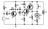
when switch S1 is depressed it shorts the supply voltage to the base of Q2, turning Q2 on. The collector of Q2 starts to pass current, charging up C3. This pulls the base of Q3 low, thus providing voltage to the base of Q2, so when the switch is unpressed, Q3 keeps Q2 on. This is a transistor latch circuit.
When an audio input comes along, the collector of Q1 wiggles, this puts a voltage on the emitter of Q2, reverse biassing the base-emitter junction of Q2, switching it off, so the light goes out
how does the circuit works. Why does the led wont turn on when the switch is off does the current wont flow from the collector of transistor 3 to the led ?
PLS. THANK YOU! I REALLY NEED THIS BADLY!!!
but is the led would still turns on without the latching transistor? (separate question) and when the switch is unpressed does the current flows through the led? why does it wont on? Is the entire circuit divided by a bridge? the dioed and the capacitor in parallel? thank you
We don't know what you are talking about since your schematic is not shown. Maybe your schematic is waiting for a moderator so see that it is not SPAM.
I have seen this one before and I found the circuit in Google. It looks like it is from the website of www.redcircuits.com but it is not there anymore.
The first transistor is an audio preamplifier for the electret mic and the 2nd and 3rd transistors are connected like a PUT (programmable unijunction transistor) that can latch on when the switch is momentarily turned on then the preamp can turn it off.
If I waste my time teaching you (I am not a teacher) then you won't learn anything.
If you look up Programmable Unijunction Transistor in Google then you might learn about them.
One website shows it like the two transistors in the Puff circuit.
The websites that have the circuit also describe how it works. You found a different website than I found because they copied the schematic and made it look different than the original schematic I posted.
This is a simple circuit in which the glowing LED can be switched OFF just by a puff. A condenser mic (M1) is used to sense your puff. When the push button S1 is pressed, the transistors Q2 and Q3 wired as latching pair gets activated and drives the LED to glow. The LED remains in this condition. When you puff on the condenser mic, the sound pressure is converted into a voltage signal at its output. This voltage signal will be amplified by the transistor Q1.Since the collector of the Q1 is coupled to the emitter of the latching pair, the pair will stop conducting when ever there is a signal from the condenser mic due to puffing and the LED will go OFF. The push button switch S1 has to be pressed again to switch the LED ON.
The circuit works as AudioGuru explained and as covered in the quote. To understand the circuit description you need to understand how the individual components work. You need to start at the beginning. You don't learn to swim by jumping into the deep end of the swimming pool. If I tell you that Q2 and Q3 form a latching circuit and you do not know what a latching circuit is or how it works we got nothing.
I suspect that Electronic Novice who started these identical threads is the same person as McFLY who asks the same kind of questions.
They both registered on the same day.
I suspect that Electronic Novice who started these identical threads is the same person as McFLY who asks the same kind of questions.
They both registered on the same day.
The circuit by Circuitstoday.com does not work. As can be expected. None of their circuits work.
Here is the corrected circuit: **broken link removed**
The main problem is the 100p on the base of the first transistor.
It should be 100n. The diode can be removed to give a slightly better effect.
A "puff" is high audio frequencies not the low frequency vowels of speech.
The electret mic with the 10k resistor powering it is about 3k ohms and the input resistance of the very high gain "C" version transistor is about 5k ohms. Then the cutoff frequency of the 100pf capacitor with the 8k load is too high at 200kHz. Maybe C1 should be 2nF for a cutoff frequency of 10kHz.
thanks to each and everyone who helped. Actually McFly is my classmate and before i was been registered to this site which he already does i asked him if he could post my project so anyone could help me because its not working and he did but later on i did register to this site and posted it again because i cant regularly see the comments because its not my account.
Thanks to everyone who helped I appreciate it, now i know why its not working its a bad circuit. I already replaced my project I should have consult it here before buying it T_T. MANY THANKS..
I e-mailed Red Circuits and informed them that the circuit has the problem with the audio coupling capacitor value that is much too low so it passes radio frequencies but does not pass audio frequencies.
Flavio at Red circuits replied and said that he tested his circuit and it works perfectly when blowing on the mic which is big (5mm diameter) and therefore it is sensitive at a distance of 10cm.
He noted that his first transistor is spec'd to be a BC550C that has a current gain of 420 to 800 and not as low as 110 for an ordinary BC550 or BC547 so it has a higher input impedance.
I have already presented a corrected circuit in #13.
It is a waste of time going to these faulty websites and trying to tell the author about their faulty circuits.
Just because a transistor has a gain of 800 does not mean it will have this gain in a self-biased stage.
This is how little Flavio knows about electronics. No wonder his circuits do not work.
I have pages of mistakes from sites like his. You can learn a lot from other people's mistakes.
The problem with most online websites that present circuits is the circuits presented were never built or actually tried. The classic "it looks good on paper" seems to apply and rather loosely. I like the old circuits by Forrest M Mimms III as they are tried and true little circuit designs. Additionally, for transistor circuits I like the circuits that can be found here. Obviously the author took the time and patience doing the math to make sure the presented material works. No clue who the guy is but his stuff works and is at least well thought out.
This site uses cookies to help personalise content, tailor your experience and to keep you logged in if you register.
By continuing to use this site, you are consenting to our use of cookies.