Continue to Site

Welcome to our site!

Electro Tech is an online community (with over 170,000 members) who enjoy talking about and building electronic circuits, projects and gadgets. To participate you need to register. Registration is free. Click here to register now.

  • Welcome to our site! Electro Tech is an online community (with over 170,000 members) who enjoy talking about and building electronic circuits, projects and gadgets. To participate you need to register. Registration is free. Click here to register now.

electronic and electrical components etc.

Status
Not open for further replies.

PG1995

Active Member
Hi

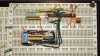
In this breadboard circuit, you can see that the wires are laid out nicely and they seem to fit tightly into breadboard holes. Where do I get these wires? What is their gauge? I see that they are single stand wires but still I don't know how to search for these wires. Please help me. Thanks.

Regards
PG
 

Attachments

  • Breadboard_counter.jpg
    Breadboard_counter.jpg
    2.9 MB · Views: 630
I have large reels (100metres) of 0.6mm single core wire in three colours and just cut what I need as I need it.
This of course may be a big outlay for you.

The wire kits as suggested above are a good idea, but will not have the wire you want when you want it!

For a CHEAP solution, have a look for some discarded CAT5 ethernet cable which has several single strand wires.
Strip the outer insulation sheath, and you have lots of single core wire to cut as required.

JimB
 
Thank you, everyone.

I have large reels (100metres) of 0.6mm single core wire in three colours and just cut what I need as I need it.

Where did you get it? They might have small reels. Could you please link me to online retailer, such as Amazon, for such reels? Thanks.

The following are also good options.
KISS: **broken link removed** (in form a kit)
RoboWanabe: https://www.hobbytronics.co.uk/cables-connectors/breadboard-wire (sold per meter)

Regards
PG
 
Last edited:
Hi

This meter reads DC volts and amperes and it looks like it can easily be used a circuit without affecting the circuit performance in any way; I mean it's function is similar to regular voltmeter and ammeter, right? The good thing about this meter is that it has a built-in shunt.

Could you please help me to locate a meter which also reads watts? Many meters I have found which also read watts, like this one, are specified for battery charging/discharging etc. (besides, they are little expensive) therefore I don't think they can be used in a circuit without disrupting the circuit. Please help me if possible. Thanks.

Regards
PG
 
PG:

Not enough information. These cheap ebay meters put the shunt into the negative line to make them cheap. Adding any sort of shunt CAN change the circuit operation.

It just depends if you want to measure the power consumption of a microprocessor in sleep or a 12 V battery with currents like 30 Amps.

Your intended application is paramount. e.g. Here is nice power meter **broken link removed** that could be used to measure 5V. Although it says 1 A, that may only be possible for USB devices, Likely it could be used for anything requiring 5V and < 500 mA.
 
Thank you, KISS.

Not enough information. These cheap ebay meters put the shunt into the negative line to make them cheap. Adding any sort of shunt CAN change the circuit operation.

Okay. Then, you can link me to some non-ebay, little expensive meter which does what I want. I want it function like a regular voltmeter and ammeter so that it does not affect the circuit operation.

It just depends if you want to measure the power consumption of a microprocessor in sleep or a 12 V battery with currents like 30 Amps.

Don't there exist some general power meters, under the range 50W, which can simply be used in a DC circuit to tell us how much power is being used? Thanks.

Regards
PG
 
Don't there exist some general power meters, under the range 50W, which can simply be used in a DC circuit to tell us how much power is being used?
The quick answer is NO, there are not.
Yes power meters exist, but they are generally used in mains powered AC circuits.

I would ask,
"Why do you want to do this?"
"What advantage do you think that it will give you?"

As a general rule, in a low voltage DC circuit, the voltage is constant, if you need to know the power or to see how the power is varying, just measure the current.

JimB
 
PG:

What I was really saying is that you need an entirely different circuit for say measuring the uA of current in sleep mode for system powered off a 1.8 V battery.
A shunt adds a voltage drop, Your application determines if it's significant. Power seems to be an evasive quantity with respect to DC. I could always point to an "electronic load" if you were powering the circuit with it.

Most handheld current meters use a shunt. Sometimes it's hard to find the "max voltage burden spec". 50 mV might not affect your measurement, but 0.3 Volts might.
Power and current are still correct with the device inserted, but will not be the same when it's removed.

Somehow, I think this has to do with your solar array? You could make one easy enough with an analog multiplier and/or the A/D on a microcontroller.

What are you looking for in terms of max voltage and resolution?
 
Thank you, Jim, KISS.

Yes, I want to use it with my solar project. I will be using a small 12V, 10W panel and 6V, 7Ah sealed lead-acid battery.

I want to use two meters - one at the input and the the other at output. Is this meter suggested by KISS in the post above a right choice? Would it affect the general circuit operation? Would it be as harmless as a regular voltmeter and ammeter? Thanks.

Regards
PG
 
It looks like there are others. e.g.: https://www.google.com/url?sa=t&rct=j&q=&esrc=s&source=web&cd=4&ved=0CH8QFjAD&url=https://www.rc-cars-planes.com/docs/wu100v2_user_manual.pdf&ei=gVuaU_XUJsGXyASEv4GABQ&usg=AFQjCNETDc4Iw22uWXJgWWTsPlyq06pmsg&sig2=_U_5AcBbG64eG2h6jX4_TQ&bvm=bv.68911936,d.aWw&cad=rja I found it on Amazon, but because of the way Amazon works, you have to find the manual elsewhere.

When you do that, you sometimes find it cheaper. Amazon is good for the reviews.

So, it doesn't seem to like negative currents. The shunt is really, really small and it uses 6 mA.

Anyway the key terms are solar, wind and RC (Radio Control).

Here is a user manual for the Winday Nation one: https://www.google.com/url?sa=t&rct=j&q=&esrc=s&source=web&cd=5&cad=rja&uact=8&ved=0CEcQFjAE&url=https://solarog.com/Manuals/WattMeterWindyNation.pdf&ei=H16aU7nyHuy0sATOgoCQBQ&usg=AFQjCNGccFKbMyXvqqZU9IvqCIj4ZhMejQ&sig2=PDYSksIreXX-9CD6w3HvAw&bvm=bv.68911936,d.cWc

and what does "4.1.2.1 Amps (A) The Amps value displayed is the average current flowing through the meter’s black wire over the last screen update interval." mean?

The current is the same through all parts of the circuit, right? Not just the BLACK wire.

These https://www.rcgroups.com/forums/showthread.php?t=1208568 guys aren't impressed.
 
Last edited:
Thank you, KISS, for searching the details to help me.

But I still don't know which meter I should use and which one is as harmless as a regular voltmeter or ammeter. In my solar project maximum current which can be reached could be taken to be 4A and maximum volts around 22V. I don't know much about this stuff so could you please help me to zero in on some particular meter(s). Thanks a lot.

Regards
PG
 
I THINK both meters are suitable, as long as the currents measured are in the same direction. What I THINK I see is no negative currents. So, it cannot go before a battery because you can charge and take current from a battery. The "harm: they do is draw 6-7 mA. So, I can see one at the array. This gives you a lot of information on the array.

You may need to a bit more searching for solar type meters or maybe use a current sensor such as these https://www.pololu.com/product/1187 and two voltmeters.
They come in various ranges and are mounted on a PCB from the guys shown. If your using a micrcontroller, you may be able to incorporate those sensors.
 
PG:

You can probably use one at the array and one at the point of use. You just can't use one at the battery, because the current may go both ways. Charging and discharging.
But subtracting total energy used and generated by the array, you can figure out how much was supplied by the battery.
 
Hi KISS

I'm sorry for returning to the discussion after days. I was busy with the exams.

I THINK both meters are suitable, as long as the currents measured are in the same direction. What I THINK I see is no negative currents.

Just to make sure. I think those "both meters" are the following ones:
1: http://www.fluke.com/Fluke/inen/Pow...shooting-Power-Meters/Fluke-345.htm?PID=56070 (post #13)
2: http://www.amazon.com/100-Amp-DC-Wa...bs_misc_1?ie=UTF8&refRID=1KDWCB2BQKZKW78KQZN7 (post #14)

The Fluke one is out of question because it's not what I want and besides I'm sure it's very expensive. But #2 from windynation is a kind of meter I want to use. Amazon lists it for $40. I need two meters which means $80. It's a school project therefore in my view it's little expensive especially when there is a possibility of finding an inexpensive alternative which will do the job. Could you please help me to find an inexpensive meter? You might suggest to use an LCD and that would be a good suggestion but this will require me to devote some extra time to the details which won't be possible for me at this stage. I want to make a working model the project as soon as possible. Thank you.

Regards
PG

PS: I don't think KISS was referring to Fluke meter. He was most probably referring to **broken link removed**.
 
Last edited:
Status
Not open for further replies.

Latest threads

New Articles From Microcontroller Tips

Back
Top