Continue to Site

Welcome to our site!

Electro Tech is an online community (with over 170,000 members) who enjoy talking about and building electronic circuits, projects and gadgets. To participate you need to register. Registration is free. Click here to register now.

  • Welcome to our site! Electro Tech is an online community (with over 170,000 members) who enjoy talking about and building electronic circuits, projects and gadgets. To participate you need to register. Registration is free. Click here to register now.

electrolytic capacitor spice model

Status
Not open for further replies.

max1000000

New Member
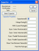
I see that the standard electrolytic cap models shipped with Multisim are in fact not polarized devices. It seems they are simple ideal capacitors with an electrolytic schematic symbol.

Does anyone have (or know a link to) a good electrolytic capacitor spice model that considers polarity and perhaps inherent series inductance, dielectric loss and leakage as well.
 
Can't you stick a resistor and inductor in series with the cap? And maybe guesstimate approximate parasitic values? If you're going to consider these don't forget about parasitic RLC on the PCB traces either.

Google and AVX can give you rough values when they analyze capacitor non-idealities for high frequency considerations.

I don't know if polarity affects anything in the simulation in the same way a simulation doesn't care about how running too much current through something will cause it to fry.
 
Last edited:
The reason there's no model for one is because the effects of reverse bias on an electrolytics capacitor aren't reliably constant between devices, manufactors or brands. There would really be no reason to model the effects of reverse bias on a cap as you simply need to design the circuit to prevent that in the first place. If you'll note as well simulators don't tell you when the conditions say a transistor or mosfet are under in the simulation would result in it's destruction, no models do this, why should a cap?
 
Linear Technology's SwitcherCAD III has these optional parameters for a capacitor. Polarized and unpolarized have separate symbols, but they have the same properties window. You would have to get the parameters from a datasheet of the part you are simulating. As has been pointed out, the characteristics during reverse bias are not modeled, because reverse bias can be destructive, or at least can cause parameters to change and/or degrade.
 

Attachments

  • cap properties.PNG
    cap properties.PNG
    12.8 KB · Views: 1,201
What about other things like the dielectric loss, and (I can't remember what it's called) but how electrolytics have a nasty habit of recharging themselves?
 
Dielectric absorption can be easily modeld by attaching another capacitor in parallel with the first one but with a high series resistance, the value of the 'parasitic' capacitor and resistor would have to be figured out from the actual device to be simulated, you're not going to find anything on the net except 'rough' approximations.
 
Sceadwian said:
Dielectric absorption can be easily modeld by attaching another capacitor in parallel with the first one but with a high series resistance, the value of the 'parasitic' capacitor and resistor would have to be figured out from the actual device to be simulated, you're not going to find anything on the net except 'rough' approximations.
Some capacitors do have a spec on percent dielectric absorption, which will allow you to choose the capacitor value, but I'v never seen a spec on the resistor value.
 
Status
Not open for further replies.

New Articles From Microcontroller Tips

Back
Top