The General Case for DC Electric motors
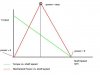
The attached diagram shows an approximate, and idealized performance curve for an electrical DC motor ... The green line is the motor output shaft torque plotted as a function of shaft speed.
Power is the math product of torque and shaft speed ....
example: (1 ft.-lbf) * (1 radian/sec.) = 1 (ft.-lbf)/sec = 1.35 watts
.... a radian is a unit angular measure ... not regarded as a standard unit
.... rpm or revolutions per minute are equal to 2Π * rev./sec * 60 sec/min.
At zero rpm, the motor torque is a maximum, but there is no shaft rotation.
Therefore the power generated is zero.
At maximum shaft speed, there is essentially no torque generated ... the no shaft load condition. Again, no mechanical power is generated.
However, at a certain mid-point on the torque vs. rpm curve of the output shaft, the product of torque and shaft speed reaches a maximum. This is the apex point of the red curve on the graph.
This is the optimum speed at which the motor should be operated to take advantage of the design and capability of this particular motor. The mechanical power which is generated at the maximum power speed point can be transferred to a gear train or transmission, and converted into a larger torque, or a greater speed as required.
If you wanted to design a super wrench with a great deal of torque, you would select a motor and connect its output shaft to an appropriately ratioed gear train ... that is, a small diameter input gear and large diameter output gear ...and then run the primary motor at its maximum power associated rpm ..... If you were to run the primary motor at the un-geared zero rpm speed, you would be severely limited in your power transfer and resulting performance.
If your design strategy is to have a high speed shaft output .... maybe for a race car .... you would connect a larger diameter gear to the motor shaft, and mesh with a smaller gear at the drive wheel .... operating the drive motor at the optimum power rpm speed. .... Just operating the motor at the no load speed .... without any intermediate gearing would be inefficient as far as power transfer is concerned.
Motor Shaft Speed Reduction
A typical problem with small hobby type DC motors seems to be in speed reduction of the output motor shaft. If the DC motor specification is for 10 thousand rpm at the no load condition, you will want to achieve an actual motor operating speed range of possibly 5 thousand rpm, for consideration of power transfer efficiency.... While at the same time, the actual speed of the drive axle might be 100 rpm.
This may be achieved by using a gear ratio of a motor to wheel reduction ratio of 50 to 1 ... The smaller diameter gear being placed on the motor shaft, and the larger diameter gear on the drive axle.
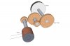
Rather than have a 1 inch diameter gear that is meshed to a 50 inch diameter gear, it is possible to use intermediate gears ... in such a manner that a 1 inch gear on the motor shaft meshes with a 3 inch diameter gear, with a second 1 inch gear installed on the same shaft as the 3 inch gear, and a final 3 inch gear installed on the final drive axle. ... 3 * 3 = 9
continuing in this manner until the desired drive axle speed is achieved.
... see attached image.
For hobby race cars, gear boxes of this nature are available from manufacturers. An example here uses a worm gear on the output shaft of the motor.:
Tamiya America, Inc Worm Gear Box Set Radio Control Slot Cars - RCSLOT.com Secure Online Store
The attached diagram shows an approximate, and idealized performance curve for an electrical DC motor ... The green line is the motor output shaft torque plotted as a function of shaft speed.
Power is the math product of torque and shaft speed ....
example: (1 ft.-lbf) * (1 radian/sec.) = 1 (ft.-lbf)/sec = 1.35 watts
.... a radian is a unit angular measure ... not regarded as a standard unit
.... rpm or revolutions per minute are equal to 2Π * rev./sec * 60 sec/min.
At zero rpm, the motor torque is a maximum, but there is no shaft rotation.
Therefore the power generated is zero.
At maximum shaft speed, there is essentially no torque generated ... the no shaft load condition. Again, no mechanical power is generated.
However, at a certain mid-point on the torque vs. rpm curve of the output shaft, the product of torque and shaft speed reaches a maximum. This is the apex point of the red curve on the graph.
This is the optimum speed at which the motor should be operated to take advantage of the design and capability of this particular motor. The mechanical power which is generated at the maximum power speed point can be transferred to a gear train or transmission, and converted into a larger torque, or a greater speed as required.
If you wanted to design a super wrench with a great deal of torque, you would select a motor and connect its output shaft to an appropriately ratioed gear train ... that is, a small diameter input gear and large diameter output gear ...and then run the primary motor at its maximum power associated rpm ..... If you were to run the primary motor at the un-geared zero rpm speed, you would be severely limited in your power transfer and resulting performance.
If your design strategy is to have a high speed shaft output .... maybe for a race car .... you would connect a larger diameter gear to the motor shaft, and mesh with a smaller gear at the drive wheel .... operating the drive motor at the optimum power rpm speed. .... Just operating the motor at the no load speed .... without any intermediate gearing would be inefficient as far as power transfer is concerned.
Motor Shaft Speed Reduction
A typical problem with small hobby type DC motors seems to be in speed reduction of the output motor shaft. If the DC motor specification is for 10 thousand rpm at the no load condition, you will want to achieve an actual motor operating speed range of possibly 5 thousand rpm, for consideration of power transfer efficiency.... While at the same time, the actual speed of the drive axle might be 100 rpm.
This may be achieved by using a gear ratio of a motor to wheel reduction ratio of 50 to 1 ... The smaller diameter gear being placed on the motor shaft, and the larger diameter gear on the drive axle.
Rather than have a 1 inch diameter gear that is meshed to a 50 inch diameter gear, it is possible to use intermediate gears ... in such a manner that a 1 inch gear on the motor shaft meshes with a 3 inch diameter gear, with a second 1 inch gear installed on the same shaft as the 3 inch gear, and a final 3 inch gear installed on the final drive axle. ... 3 * 3 = 9
continuing in this manner until the desired drive axle speed is achieved.
... see attached image.
For hobby race cars, gear boxes of this nature are available from manufacturers. An example here uses a worm gear on the output shaft of the motor.:
Tamiya America, Inc Worm Gear Box Set Radio Control Slot Cars - RCSLOT.com Secure Online Store
Attachments
Last edited:
