WJoubert
New Member
Hi
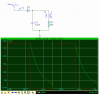
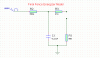
I want to build a simple (I think) energizer.
Details are as follows=
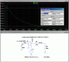
Input Voltage: 9Vdc to 12Vdc
Current consumption: 50mA @ 9Vdc 80mA @ 12Vdc
Output Open V: 4000V
Output into 500 OHMS: 2800V
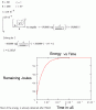
Energy over 500 OHMS: 0.9J
Impulse Rate: 1.1 Second
Impulse duration: 250uS
Can anyone please help
Thanx
I want to build a simple (I think) energizer.
Details are as follows=
Input Voltage: 9Vdc to 12Vdc
Current consumption: 50mA @ 9Vdc 80mA @ 12Vdc
Output Open V: 4000V
Output into 500 OHMS: 2800V
Energy over 500 OHMS: 0.9J
Impulse Rate: 1.1 Second
Impulse duration: 250uS
Can anyone please help
Thanx
")