Mosaic
Well-Known Member
Hi all:
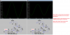
I was fooling around with a basic amplifier interface for a generic electret (from Newark) and I came up with this design that seems to exhibit some low noise floor properties with better low end frequency response. (I wanted it to feed a PIC comparator so the DC offset is good for me).
I note that once the LED isn't saturated (lit) the noise floor is better than the original circuit.
Original circuit:
**broken link removed**
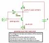
Modified Circuit:

Perhaps those with experience in audio amps etc. can pitch in. This is purely experimental here.
I was fooling around with a basic amplifier interface for a generic electret (from Newark) and I came up with this design that seems to exhibit some low noise floor properties with better low end frequency response. (I wanted it to feed a PIC comparator so the DC offset is good for me).
I note that once the LED isn't saturated (lit) the noise floor is better than the original circuit.
Original circuit:
**broken link removed**
Modified Circuit:
Perhaps those with experience in audio amps etc. can pitch in. This is purely experimental here.