Continue to Site

Welcome to our site!

Electro Tech is an online community (with over 170,000 members) who enjoy talking about and building electronic circuits, projects and gadgets. To participate you need to register. Registration is free. Click here to register now.

  • Welcome to our site! Electro Tech is an online community (with over 170,000 members) who enjoy talking about and building electronic circuits, projects and gadgets. To participate you need to register. Registration is free. Click here to register now.

Elec. mic. array with active filter and amp.

Status
Not open for further replies.

Pax Writer

New Member
Hey experts!
I've gotten around to constructing my own first amplifier circuit.
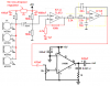
Its supposed to be a listening device with two channels. Each of the channels gets its inputs from an array of four electret microphones.
Each microphone has its own preamplifier, and these four pre amps are then mixed in a Sallen-Key low-pass filter which also works as an adder for the four pre amps.
After the low pass filter, there is a general amplifier before the signal is fed to a pair of head phones via a jack.

I have attached the schematic to this thread, and I was hoping some of you enlightened people would take a look at it and help me point out the most obvious (and hopefully also the less obvious) mistakes.
In the case where I don't know the component value, I've left the value out altogether, and in these cases, you are also most welcome to comment and suggest.

The amplification of each of the blocks in the diagram as well as overall is as of yet undetermined, simply because I don't know what kind of signal levels I can expect from each of the MCE100 microphones, but I guess I'll have to experiment my way out of that. I've been unable to find a data sheet for this little gadget.. Which is strange, considering how common they seem to be..

In any case, all help will be very greatly appreciated! If you have any questions, I'll also be happy to answer as I best can.

Thanks in advance.

Pax
 

Attachments

  • MT17 - Sound Amplifier -1.pdf
    101.5 KB · Views: 398
On the output: The LM324 max output current is about 10 mA. Into 8 ohms, this is less than a milliwatt. Will this be loud enough?

IC2-C and IC2-E don't have bias resistors.

Is your preamp topology correct? R4, 9, 14, and 19 seem to do nothing. Should they be arranged like R24?

C10 and C18 are a lot larger than they need to be. If you reduce them to 330n, and re-simulate your filter, you might like the way the additional pole works with the existing low pass.

The 47K and 100K bias resistors could be larger (470K?) saving almost a milliamp total.

The microphone bias resistor is too low. The MCE100 is specified to use less than 500 microamps. Replace the 1K resistors with 47K, producing a bias of about 180 microamps.

C2, 4, 6, 8, 11, 12, 19, 20, 16, 17, 24, and 25 should be resistors.
 
Last edited:
With normal speech (normal voice level at about 1 meter distance, 85 dbA) the microphone will produce approximately 2 millivolts.

(5.6 mV/Pa)
 
The lowpass filter must be fed from a low impedance (the output of an opamp), not four 1k resistors in parallel.

For a boardroom conferencing system, I connected 10 electret mics in parallel, all powered by one 1k resistor and they worked and mixed their signals fine. I used a regulated and filtered supply for the mics.

Your circuit doesn't have any filtering for the power to the mics so it will probably motorboat as the 9V battery voltage jumps up and down from the opamp current, then the jumping signal is the input to the opamps.
 
For audioguru:
1. Are you proposing, that I connect all the mics with pin 2 to GND and pin 1 to R1, and then through C1 to the first op amp? So that all pin 1s are connected to the same net with only R1 (which according to mnearys advice should probably be around 10k, I guess)?

2. When you say filtering, what exactly does that imply? Could that be a series regulator, for example a 7805, with decoupling?

3. The signal feed to the Sallen-Key-filter was an attempt to use the filter as a mixer as well, but I guess, if you suggest simply parallelling the mics as I wrote in question 1, there is no reason why the filter wouldn't be able to get its signal directly from the preamplifier's output...
 
Last edited:
To mneary:
Your comments leads me to some questions, which I hope is okay. They are:
1. On the output. I see your point. I made a very rough prototype on a breadboard and connected my Sennheiser head phones, which did result in audible sound. But maybe I could simply build a small common collector circuit just before the jack. Do you think that would work?

2. With regards to the bias resistors for the op amps, I'm not quite sure how to calculate the needed sizes. How can I do that?

3. R4, R9, R14 and R19 are there because I snatched this circuit construction from a tutorial on the net. I don't remember what the explanation for that resistor was, but when I experimented with removing them, it had no audible effect, so I guess they're superfluous...

4. The Sallen-Key filter was calculated using TIs "How to build filters in 30 seconds", which estimated that the Cin for that circuit should be 100-1000 times greater than C13, which I guess is to minimise its influence on the frequency characteristics of the circuit. Wouldn't a 330n be too small?

5. With regards to the mystery Cs... That's a bit embarassing... The reference designators should have been R2, 4, 6, 8, etc... Thanks for spotting that :)

These are a lot of questions, and as you can probably tell from them, I'm quite new to filters and analogue design in general, so this is also a great opportunity for me to learn new things. I hope you'll feel like taking the time to answer my questions :)

Also: This listening device is supposed to pick up rather faint and distant sounds and amplify them to an audible level, and the MCE100 is the only mic I have. Do you think it will do, or should I look for an alternative.

And finally: Would you happen to have the data sheet for the mics? I couldn't find them anywhere.
 
NOTE: If you can find the time to answer my new questions, I'll take the liberty of correcting the schematic and re-post it, to make sure I didn't misunderstand anything ...

Thanks for your great help so far.
 
Most cheap electret mics have about the same sensitivity, operating current and frequency response.
You used the very old, distorting and noisy LM324 opamp. A low noise, low distortion dual TL072 or quad TL074 makes a good mic preamp.
I have added filtering for the power for the mics with a low-dropout 5V voltage regulator and two capacitors.
I have added a gain of about 22 times for the first opamp. Its very low output impedance drives the lowpass filter properly.
I have increased the values of the resistors in the lowpass filter so an opamp can drive it, and reduced the values of the capacitors to match.
I have added an LM386 small power amp with a gain of 10 to drive headphones with an impedance down to 8 ohms.
 

Attachments

  • mic preamp.PNG
    mic preamp.PNG
    22.8 KB · Views: 903
Hi Audioguru
I spent a little time drawing your schematic in Powerlogic, but changing it a little bit according to which parts I actually have, and I have a few more questions, if you don't mind:
1. I only had 7805s to use as voltage regulators for the mics.. Will they suffice?
2. I can't quite figure out the feedback loop in the preamp. My assumption is that the circuit will cut off the very lowest frequencies (fo= approx. 33Hz)... Am I way off?
3. What is the gain and fo of the final amplifier? R17 appears to be 10R, which means the fo for the RC-circuit would be 330-something kHz. I know I must be completely off on this one :)
4. Wouldn't the final amplifier need bias on the - input? (I guess this could have something to do with me replacing the LM386 with a LM384 which happened to be the type I had on stock.. Although I'm not quite sure if it'll get a sufficiently high supply voltage)..

I hope you'll give me some hints on the frequency dependent feedbacks, since this is probably where I lack the most knowledge, but also if you could find time to comment on my reckless replacement of the parts you recommended, I would be grateful :)

And.. Thanks a bunch so far!

The new schematic was attached with the name MT17 - Sound Amplifier -2.pdf
 

Attachments

  • MT17 - Sound Amplifier -2.pdf
    100.4 KB · Views: 329
Last edited:
Hi Pax,

Sorry if I'm interrupting but:

7805 is OK.
Right, lower cutoff of infrasonics is about 34 Hz.
Check out and compare datasheets for LM384 and LM386 at **broken link removed** . Notice the manufacturer's suggested RC snubber circuits on the output of each type of IC are different. These are used to prevent these cheap IC op-amps from breaking out into oscillation. (Something to do with virtual inductance in the bipolar output transistors.)

The data sheets also have gain configuration information.

Cheers, Bob
 
Last edited:
Hi Bob
You're not interrupting at all - I appreciate that you took the time to answer. What's all that about infrasonics? In which way is it harmful to the circuit?
And is it something that should always be designed into a preamp?
... I just re-read the data sheet for the LM384, and it says that the construction of the inputs allow it to be referenced to ground, which I guess is why the - input wasn't biased externally (?). I also just now noticed the external RC-circuit on the output, but the data sheet doesn't explain why to construct the circuit like that, so I'll take your word on it :)
On top of it all, I noticed the fixed gain of 34dB :D Amazing what a person can fail to see despite the obviousness (if there is such a word in English).

Thanks Bob!
 
Pax Writer said:
1. I only had 7805s to use as voltage regulators for the mics.. Will they suffice?
Yes if there is a 9V power supply, no if you use a 9V battery that quickly drops its voltage to only 7.2V where some 7805's don't work. The 9V battery's voltage drops further.
A 5V low-dropout regulator works fine until its input voltage drops to only 5.4V. I use National Semi's LM2931AZ-5.0 but all semiconductor manufacturers make similar ones.

2. I can't quite figure out the feedback loop in the preamp. My assumption is that the circuit will cut off the very lowest frequencies (fo= approx. 33Hz)... Am I way off?
The response is down only 3dB at 34Hz which is barely noticeable. It is down only about 6dB at 17Hz and is down 12dB at 8.5Hz. The cutoff is gradual.
Are you listening to rumbling earthquakes?

3. What is the gain and fo of the final amplifier? R17 appears to be 10R, which means the fo for the RC-circuit would be 330-something kHz. I know I must be completely off on this one :)
I am glad you later looked at the gain in the datasheets. The LM380 is similar and was made first. They explain in its datasheet or in an applications note that they oscillate at a very high frequency when the speaker's inductance causes the load impedance to be high at high frequencies. The 10 ohms resistor becomes the load at very high frequencies to keep the amps stable.

4. Wouldn't the final amplifier need bias on the - input? (I guess this could have something to do with me replacing the LM386 with a LM384 which happened to be the type I had on stock.. Although I'm not quite sure if it'll get a sufficiently high supply voltage)..
I am glad that you looked at the 0V input bias requirement on the datasheets. The minimum supply voltage for an LM384 is 12V, the minimum for an LM386 is only 4V to 5V. Your choice.
 
Hi again Audioguru

I think finally most of my questions have been answered, thanks in very great part to your fantastic help. Thank you very much.
I will try to get a hold of the low-dropout regulator - I wasn't even aware that such an IC existed, if we were not talking about a switch mode IC.
With regards to the low frequency, I don't plan to listen to earth quakes, but I was only trying to figure out the practical reasons for the introduciton of this limit in the circuit. Maybe you had some experience which dictated this, which I would have to research and spend a great deal of time to find out - So I thought it would simply be easier to ask :)
And finally, with regards to the LM384/386-issue, I can see now that I'll have to get the op amp you suggested, because I need to be able to power the circuit with a 9V battery.

Thanks again.
 
Pax Writer said:
With regards to the low frequency, I don't plan to listen to earth quakes, but I was only trying to figure out the practical reasons for the introduciton of this limit in the circuit. Maybe you had some experience which dictated this, which I would have to research and spend a great deal of time to find out - So I thought it would simply be easier to ask :)

Pax,

Infra sonic signals are below the audio range. For audio purposes, you cannot hear them, they can be quite high amplitude and tend to interfer with the signals you do want to hear. Examples are: Warped phono records make the woofers in your speakers wobble in and out over huge excursions. This added inaudible noise can also interfer with older tape recording equipment...saturating the tape and causing distortion.

Suggestion: When you get this built, use wind breaking socks over the microphones to help eliminate the wind noise. They attenuate frequencies below the audio spectrum. Just use little foam rubber balls.

Cheers, Bob
 
Hi Pax,
If you aren't listening to earthquakes, then what low frequency sounds are you listening to?

The lowest frequency of a huge pipe organ is 16Hz.
 
You could use a suitably sized DC blocking capacitor to eliminate noise.

I thought most people can't hear below 20Hz so a 16Hz note on a pipe organ won't be hurd by most people; well they'll be able to hear the harmonics of course.

There are many natural sources of infra sound, tornadoes, volcanoes and thunderstorms spring to mind.
 
The frequency response of your hearing doesn't abruply stop at 20Hz. It needs a little more volume at 16Hz to hear it. A big pipe organ plays 16Hz very loudly so most people can hear it and feel it.

Your body gets vibrated at very low frequencies then your brain concentrates on the vibration instead of the sound.
 
I wonder what the absolue cut off point of the human hearing range is, I've tried playing a 10Hz sine wave froma sub woofer and I couldn't hear it even standing right next to the speaker!
 
To Bob: Thanks for the explanation. This thread really shows one of the biggest advantages of the net. In this case, I've had the opportunity to learn from the experience of two much more capable electronics people than myself, even though we probably live several thousand km apart :) I had no idea about the phenomena you just described until now, and its always nice to know why I do things. Thanks.

To Audioguru: I'm not listening to any low frequencies in particular. In fact I only expect to hear sounds within 300 Hz to around 4-5kHz. I was simply curious as to what prompted this frequency response in the pre amp, since I suspected your motive was reasonable and necessary, and I thought it would be nice to know about :)

To finally describe what I'm doing, it is a sound amplifier for use in survival games which I play. I tend to rely quite strongly on my hearing, when I hide, but unfortunately my hearing is impaired from birth to around 65-70% of normal people. Not much, but I lose an edge there, so I wanted to be able to pick up faint sounds occasionally.
I know this sounds kind of silly, but later on I plan to use this kind of circuit for something a little more serious too. This project is mainly supposed to give me just a very little bit of experience, before I get more serious :)

In any case, you've been a great help. Thank you.
 
Status
Not open for further replies.

New Articles From Microcontroller Tips

Back
Top