I am trying to set up my ECCP1 on the 16f1829 to output single waveform PWM to two pins--right now P1A and P1B. I get a good build (other than bank errors) and the Pickit3 says it programmed. I am working on my turn signal controller--just experimenting now.
https://www.electro-tech-online.com/threads/stuck-planning-my-turn-signal-module.123061/
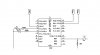
Attached is the schematic for my basic test circuit and my rudimentary code. I started with 16f1827TEMP.asm since there are no 1829 templates available. I am trying to make the 2 leds light up at 30% duty cycle, then go bright to 90% for the button press, then dim again when the button is released. Right now I get NOTHING. What did I miss please???
Thank you!!!!!!
https://www.electro-tech-online.com/threads/stuck-planning-my-turn-signal-module.123061/
Attached is the schematic for my basic test circuit and my rudimentary code. I started with 16f1827TEMP.asm since there are no 1829 templates available. I am trying to make the 2 leds light up at 30% duty cycle, then go bright to 90% for the button press, then dim again when the button is released. Right now I get NOTHING. What did I miss please???
Thank you!!!!!!
Code:
;******************************************************************************
;   This file is a basic code template for code generation on the             *
;   PIC16F1827. This file contains the basic code building blocks to build    *
;   upon.                                                                     *
;                                                                             *
;   Refer to the MPASM User's Guide for additional information on             *
;   features of the assembler.                                                *
;                                                                             *
;   Refer to the respective data sheet for additional                         *
;   information on the instruction set.                                       *
;                                                                             *
;******************************************************************************
;                                                                             *
;    Filename:        16f1829 flash.asm                                       *
;    Date:                                                                    *
;    File Version:                                                            *
;                                                                             *
;    Author:                                                                  *
;    Company:                                                                 *
;                                                                             *
;                                                                             *
;******************************************************************************
;                                                                             *
;    Files Required: P16F1829.INC                                             *
;                                                                             *
;******************************************************************************
;                                                                             *
;    Notes:                                                                   *
;                                                                             *
;******************************************************************************
;                                                                             *
;    Revision History:                                                        *
;                                                                             *
;******************************************************************************


	list		p=16f1829      ; list directive to define processor
	#include	<p16f1829.inc> ; processor specific variable definitions

;------------------------------------------------------------------------------
;
; CONFIGURATION WORD SETUP
;
;
;------------------------------------------------------------------------------

    __CONFIG _CONFIG1, _FOSC_INTOSC & _WDTE_OFF & _PWRTE_OFF & _MCLRE_ON & _CP_OFF & _CPD_OFF & _BOREN_OFF & _CLKOUTEN_ON & _IESO_OFF & _FCMEN_OFF
    __CONFIG _CONFIG2, _WRT_OFF & _PLLEN_OFF & _STVREN_OFF & _BORV_19 & _LVP_OFF

;------------------------------------------------------------------------------
; VARIABLE DEFINITIONS
;
; Available Data Memory divided into Bank 0-15.  Each Bank may contain
; Special Function Registers, General Purpose Registers, and Access RAM
;
;------------------------------------------------------------------------------

    CBLOCK 0x20 ; Define GPR variable register locations

    ENDC

SW1	Equ	4			;Button on RBx

;------------------------------------------------------------------------------
; EEPROM INITIALIZATION
;
; The 16F1827 has 256 bytes of non-volatile EEPROM, starting at address 0xF000
;
;------------------------------------------------------------------------------

DATAEE    ORG  0xF000
    DE    "MCHP"  ; Place 'M' 'C' 'H' 'P' at address 0,1,2,3

;------------------------------------------------------------------------------
; RESET VECTOR
;------------------------------------------------------------------------------

    ORG     0x0000            ; processor reset vector
    PAGESEL START
    GOTO    START             ; When using debug header, first inst.
                              ; may be passed over by ICD2.

;------------------------------------------------------------------------------
; INTERRUPT SERVICE ROUTINE
;------------------------------------------------------------------------------

    ORG      0x0004

;------------------------------------------------------------------------------
; USER INTERRUPT SERVICE ROUTINE GOES HERE
;------------------------------------------------------------------------------

; Note the 16F1827 family automatically handles context restoration for
; W, STATUS, BSR, FSR, and PCLATH where previous templates for 16F families
; required manual restoration.  Shadow registers store these SFR values, and
; shadow registers may be modified since they are readable and writable for
; modification to the context restoration.

    RETFIE                    ; return from interrupt

;------------------------------------------------------------------------------
; MAIN PROGRAM
;------------------------------------------------------------------------------

START
;set up intosc
	MOVLW	b'01111000'            	; SET INTERNAL OSCILLATOR FREQUENCY
			;'0-------'	PLL OFF
			;'-1111---'	16MHz CLOCK SPEED, SEE DATASHEET PAGE 71
			;'-0000---'	31KHz CLOCK SPEED
			;'------00'	SYSTEM CLOCK SET BITS TO INTOSC--set in config so actual value irrelevant
	MOVWF	OSCCON    		; INITIALIZE clock


;*********set up ports and pins

; may need to use APFCON0 OR APFCON1 registers to set function of ECCP pins


	CLRF	PORTA		; PortA all low
	CLRF	PORTB		; PortB all low
	CLRF	PORTC		; PortC all low

   	MOVLW 	b'00000000'	;
   	MOVWF 	TRISA		;PORTA outputs
	MOVWF 	TRISC		;PORTC outputs


   	MOVLW 	b'11111111'	;set PortB as inputs
   	MOVWF 	TRISB

;********setup ECCP1**********

	MOVLW	b'00011010'	;
				;'00------'		CCP1 timer 2
				;'--01----'		CCP2 timer 4
				;'----10--'		CCP3 timer 6
				;'------10'		CCP4 timer 6
	MOVWF	CCPTMRS		; Set Pwm timer sources  page 237

	MOVLW	b'11111001'
	MOVWF	PR2		; 249


	MOVLW	b'00000111'	;
	MOVWF	T2CON		; Prescaler 1:16 (bits 0-1) and postscaler 1:1 (bits 3-6)

	MOVLW	b'01001010'	; bits 2-10 of 10 bit pwm for 30% duty cycle
	MOVWF	CCPR1L		;

	MOVLW	b'00111100'	;
				;'00------'		Single Output ECCP
				;'--11----'		PWM Low side bits
				;'----1100'		Set ECCP pins P1A,C,B,D active high
				;
	MOVWF	CCP1CON		; Set Pwm Mode ECCP1  page 236
				;
	BSF	T2CON,TMR2ON	; Enable PWM
	GOTO	Loop		; Reset -> init


; 1/Fosc = Tosc  (1/ 16 Mhz = 6.25 x 10^-8)
; PWM Period = [(PRx)+1] * 4 * Tosc * TMR2 prescale value
; PWM Period = [249+1] * 4 * 6.25 x 10^-8 * 16
; PWM Period =  .001sec = 1000Hz


;The following steps should be taken when configuring the CCP module for PWM operation.
;1. Set the PWM period by writing to the PR2 register.
;2. Set the PWM duty cycle by writing to the CCPRxL register and CCP1<4:5> bits of CCPxCON register.
;3. Set the TMRx prescale value and enable Timerx by writing to TxCON register.
;4. Configure the CCPx module for PWM operation.

;------------------------------------------------------------------------------
; PLACE USER PROGRAM HERE
;------------------------------------------------------------------------------


Loop	btfsc	PORTB,	SW1
	call	bright
	btfss	PORTB,	SW1
	call	dim
	goto	Loop

bright
	MOVLW	b'11100000'	; set bits 9-2 for 90% duty cycle
	MOVWF	CCPR1L
	return

dim
	MOVLW	b'01001010'	; set bits 9-2 for 30% duty cycle
	MOVWF	CCPR1L
	return

	END

; That's all folks!