Continue to Site

Welcome to our site!

Electro Tech is an online community (with over 170,000 members) who enjoy talking about and building electronic circuits, projects and gadgets. To participate you need to register. Registration is free. Click here to register now.

  • Welcome to our site! Electro Tech is an online community (with over 170,000 members) who enjoy talking about and building electronic circuits, projects and gadgets. To participate you need to register. Registration is free. Click here to register now.

Earliest voltage indicator

Status
Not open for further replies.

throbscottle

Well-Known Member
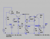
I've designed this little circuit to indicate whether V1 or V2 comes up first. In simulation at least it works tolerably well. It's to indicate if the vpp/vdd priority switch has functioned correctly on the pic programmer I've nearly finished. Whichever transistor switches on first locks out the other one.

Ideally it would have gain and not be powered by the sources it is giving an indication of! But I can't see a way to do that with only 2 transistors.

Just thought I'd share it anyway.
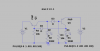
 

Attachments

  • which-voltage-first.png
    which-voltage-first.png
    12.9 KB · Views: 192
  • first-voltage-indicate.asc
    1.6 KB · Views: 125
If you don't mind using a logic function, a D flip-flop might do what you need.

Q will be high if the D pin goes high before the Clock pin does.
 
Good idea, but I'll stick with the trannys :) I've built it on a little piece of Veroboard and it's crammed full as it is.
 
It's a beautifully elegant symmetrical circuit, but could have been drawn nicer I think (ie symmetrical) more like a multivibrator (that the design borrows from).
 
Ok, after building it on a breadboard and messing with it all day I really appreciate how useful some extra diodes and capacitors can be...

The led which was not supposed to come on on either side was glowing a bit, also ran into serious issues when using different colour led's, maybe because they're very old. After messing about with pullup resistors, generally experimenting with different values and alternate transistors, I put diodes in series with the bases of the transistors to improve the switching, which worked great when poked voltages onto the emitters direct from the psu. However trying it with the actual source voltages brought me back to the original issue with the off led being Mr Glowey. Eventually realised that because the priority switch is dependent on vpp, which is slow to come up, the off side had time to establish a bit of current before the on side was able to block it. Tried capacitors in parallel with the extra diodes, which cured that problem. So it works nicely now.

Because vpp is sourced via a 15k resistor from a 45v supply (it's just how the booster ended up) with a 13v zener, I needed some current gain, hence the addition of a 3rd transistor.

Suddenly Chris's flip-flop looks a lot more attractive!
 

Attachments

  • which-voltage-first-real.png
    which-voltage-first-real.png
    9.7 KB · Views: 164
Shoot, there goes the elegant symmetry. ;)

Here's a way to keep the symmetry and also keep the design real small? It's untested and I thought it up real quick so there may be issues with it.

(edit) Just realised there will be a current path through the LEDs to the bases, so it needs additional resistors to bias the trannies off, or two schottky diodes between the collectors and bases. I did want to avoid the need to use a special (low Vf) diode but maybe that's the best way to go?
 

Attachments

  • first_latch.gif
    first_latch.gif
    4.1 KB · Views: 164
Looks remarkably similar to one of my early abandoned attempts! However I tried it in LTSpice (too late to tinker for real now), simulation works quite nicely with normal 1N4148 diodes - schottky ones gave a nasty spike. Resistors between e and b don't really do anything. I'll give it a go for real tomorrow. Also much more attractive because it uses npn transistors which I have a lot more of. Thanks!
 
Ok I built using a couple of BC458's (at least I think they were, shed locked now so I can't easily go and look) old and plentiful anyway, and 1N4148's for the diodes. I don't have any schottky's apart from big beefy ones with a Vf close to a normal diode, so didn't try those. Was rubbish - one led on and the other one half on :(. Didn't try with pull down resistors, maybe I should.
 
This works in simulation and maintains the symmetry....
FirstPastThePost.gif
 
Nice one! That's fixed the problem with the diode drop being too large, as you've balanced that with another diode drop. That saves the need for specialty low-Vf diodes.

If someone has small schottkys available they could use those and just use 2 diodes total, although it still might need low Vce (saturation) transistors. I normally reach for my bag of BC337/327 for these type apps, those transistors will have <0.1v Vce when turned on (and at a low current).
 
Status
Not open for further replies.

Latest threads

New Articles From Microcontroller Tips

Back
Top