Continue to Site

Welcome to our site!

Electro Tech is an online community (with over 170,000 members) who enjoy talking about and building electronic circuits, projects and gadgets. To participate you need to register. Registration is free. Click here to register now.

  • Welcome to our site! Electro Tech is an online community (with over 170,000 members) who enjoy talking about and building electronic circuits, projects and gadgets. To participate you need to register. Registration is free. Click here to register now.

Eagle: through hole and SMD

Status
Not open for further replies.

zachtheterrible

Active Member
Since Ive been starting to use SMD, ive run into a problem:

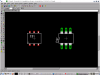
Whenever you place a component, whether it be SMD or through-hole, pin 1 always comes up in the same place: upper left hand side. Shouldnt SMD stuff have pin 1 in the upper right hand side?

It will not work because SMD and through-hole are not in the same position. They are mirrored to each other.

Kind of hard to explain :lol: does anyone catch my drift?
 
Why would surface mount components have their pin 1 at the upper right position?

My TQFP packages all show pin 1 being at the lower left position.

But why would it matter anyway? Can't you rotate the component and position pin 1 where you want it?...
 
I've never seen SMD with pin 1 on the right side. It's top left on dual row pkgs just like a TH DIP.

Perhaps you are seeing SMDs as being on the other side? Neither Eagle nor any other tool I know of sees it this way. SMD and TH are assumed to be on Top unless you choose to flip it. View from above is always the default view.
 
Ok, actually pin 1 is on the bottom left by default, my bad, but that doesnt matter :lol:

My point is this: On a one-sided board, SMD is on the bottom of the board and throughh-hole are on the top of the board. If you are looking at a SMD chip and a through-hole chip, pin 1 will be at the same place on both chips. Flip the SMD chip upside down, like you would for a single-sided board to place it on the bottom, and pin 1 will now be mirrored relative to the through-hole component. This is not the case in eagle though: Take a look @ my screenshot.
 

Attachments

  • snapshot1.png
    snapshot1.png
    35.5 KB · Views: 903
Oh I see.

So what we're saying here, is that when using Eagle, viewing the circuit from above, top side up, if you add a SMT component on a single sided board, you need to select the bottom layer (or the bottom side, where the copper is) and mirror the component yourself... Or somehow flip the board, just like you'd do in real life, place the SMT component, and then you'd see pin 1 top left when going back to original top side up view.

Am I understanding this right?
 
In the pic above, the SMD component is still on the top of the board.

You want want it on the bottom side, correct?

If you perform a "mirror" on the component, it will go to the bottom layer. You will notice that the pins turn blue (instead of red). The pins should still be in the correct position (if you imagine yourself looking at the bottom of the board)

I haven't experienced any mirroring problems by doing that.
 
Like Phasor said, you need to 'mirror' the SMD part. It's the button right under the 'move' button that is currently selected on the screenshot above. The outline colour should turn blue. The SMD placement defaults to the top layer and you want it on the bottom layer.
 
Slightly related: Can someone link me to the smd library? I've googled it but this library never comes up.
 
Last edited by a moderator:
Status
Not open for further replies.

Latest threads

New Articles From Microcontroller Tips

Back
Top