Continue to Site

Welcome to our site!

Electro Tech is an online community (with over 170,000 members) who enjoy talking about and building electronic circuits, projects and gadgets. To participate you need to register. Registration is free. Click here to register now.

  • Welcome to our site! Electro Tech is an online community (with over 170,000 members) who enjoy talking about and building electronic circuits, projects and gadgets. To participate you need to register. Registration is free. Click here to register now.

Eagle Software Query

Status
Not open for further replies.

Electrix

Member
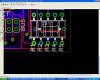
I am new to Eagle Software from Cadsoft .. I have made a simple circuit and then converted it to a Board, then with the Autorouter function, transformed it into a PCB Layout. However, I wish to change (increase) the pad and via diameters. I'm not sure of how to do this.. :roll:
Please help me
:?

Thanks
 
here's a good tutorial on eagle
but for now it's under the edit menu ,just click CHANGE and you will see another options menu for pads and via's click diameter click the size you want then click on the pad to change it
 

Attachments

  • tutorial-eng.pdf
    365 KB · Views: 520
bbarney said:
here's a good tutorial on eagle
but for now it's under the edit menu ,just click CHANGE and you will see another options menu for pads and via's click diameter click the size you want then click on the pad to change it

Yes, I had seen that..however thats possible when you put a new via/pad.. what I want is to change their diameters together before/after autorouting the connections. :roll:
 
You probably can't make the pad diameter larger after autorouting because the autorouter only guarantees the pad-to-wire clearance listed in your specs. It can't push the wire routing further out.

I think there's a place to specify via diameter, since they're created by the autorouter. However pads are part of the package. I have to wonder, why would you even want to do this?

I've done some ops where I changed the Name/Value text size across the entire board, but I don't know about pad size.
 
Other thoughts...
There are almost always more than one kind of pad on the board. So if you were somehow able to script this change, is every pad going to be changed to the same type?
If you tried to make a round pad an oval pad the scripting would have no way to address the issue of "direction". And I've never seen anything in the interface which would imply the board layout tool can be used to pick up and manually modify a part pad, so there'd be no way to do it manually either.

I'm still thinking it's not possible. I could change the text sizes used for names/values, those are attached to the components too but they are still individually recognized in the layout tool once you've Smashed it. Nowhere does the tool seem to have the ability to do a sort of Smash where you could dissociate the device's pins- nor would it make any sense to do so.

If you have a specific device where you want to use bigger pads with, you can make a new Package and then just include that package in the existing Component. I guess you'd do that if you had thermal or mechanical reasons to use larger pads, but that should be rare.
 
I am driven into deep frustration... :x :x I can't get a particular package for a resistor.. Here's what I want... Part: 0207/10,R,0207/10

When I choose a resistor, I normallt go into rcl lib and choose the US Resistor menu and choose 0207/10 part... the problem though is that this package has a octagonal shaped pad ... thas the reason why I had mentioned my concern for increasing the dia of the pad... BUT there is a file called 'hexapod.brd' in Eagle which has resistors in the 0207/10 in r.lbr which has a round shaped pad... WHICH IS WHAT I WANT...

I just cant find the r.lbr in the library tree ...
ps: I have the Eagle 4.16 Edn for Windows Light Edition

Request you to please help me out ... the PCB designer has asked for rouned pads only :(
Here's the attachment.. note that I have highlighted the resistor with rounded pad package and have placed the resistor with octagonal package.. once again my query is HOW DO I CHOOSE THE ROUNDED PACKAGE RESISTOR ?
 

Attachments

  • pcb_886.jpg
    pcb_886.jpg
    150.2 KB · Views: 536
Electrix said:
BUT there is a file called 'hexapod.brd' in Eagle which has resistors in the 0207/10 in r.lbr which has a round shaped pad... WHICH IS WHAT I WANT...
once again my query is HOW DO I CHOOSE THE ROUNDED PACKAGE RESISTOR ?
This is one of Eagle's major weaknesses, very poor database management of parts.
I don't know where to find r.lbr, but if you can load the hexapod board, the r.lbr has to be available or it wouldn't be able to load it.
You can take the "normal" rcl resistor library and simply make a new resistor package with round pads, then add that to the resistor component as another package option. The downside is that if you install a new copy of Eagle, it's going to copy over that stock library and clobber it. And if you deliver a design relying on a modified rcl lib the recipient is going to have trouble opening it without clobbering his own rcl.lib file, which would be unfortunate if he modified that file for his own purposes. So I kinda recommend a myComponents.lbr that will never be clobbered. The downside then is that there's no existing array of resistor packages, symbols, and components in your lib. This is the evil of Eagle's lib management.

I know this wasn't your question, but why the hell would he object to hexagonal pads? Hex pads make slightly better use of board space; for a given clearance and 0/45/90 deg trace orientation hex gives you the most copper on a pad. The "points" are only a potential issue at such high freq you'd probably not be using Eagle to route it!
 
Oznog said:
I know this wasn't your question, but why the hell would he object to hexagonal pads? Hex pads make slightly better use of board space; for a given clearance and 0/45/90 deg trace orientation hex gives you the most copper on a pad. The "points" are only a potential issue at such high freq you'd probably not be using Eagle to route it!

I agree with you Oznog that having hex/ortho pads does have its advantages ... but since I'm new to designing PCBs I'm totally inexperienced and have no idea whether this PCB making guy is correct in his suggestion. Though I thinkthat rounded shaped pads are larger in terms of surface area and I think this is what the PCB designer guy wants ..
In any case I was wondering that PCB layout's on the net & mags have their resistor pads much larger than what I had drawn (with the ortho shaped).. what is the reason for this ?? Is that their Pad dias are more or are they printing out a 2:1 scale layout ?? I'm really confused abt the size of my pad .. its really tiny and this is what is causing concern to the designer too.. he fears possible errors while making the PCB... Again plase help me on the above query ... Thanks
 
Oznog said:
I don't know where to find r.lbr, but if you can load the hexapod board, the r.lbr has to be available or it wouldn't be able to load it.

Nope, tried like hell.. cant find that library ... looks like they'v made this board in some other edn of Eagle(which has r.lib) and then included this in my edn ... However I can copy the package ... so maybe the package is hidden in somewhere ??
 
all the versions of Eagle I've worked with keep the regular resistors in rcl.lbr ... I've never seen r.lbr!

so if you want round pads, then copy rcl.lbr to a different directoy (outside eagle), and name it something like rcl-roundpads

now open that library, and edit the parts you need to have round pads

save your changes, and go into your schematic

type this command

UPDATE rcl = c:\newlbr\rcl-roundpads.lbr;

the semicolon is important, it tells eagle to check all parts

this will replace any and all parts in the old rcl library with parts from the new library

alternately, you can also do a CHANGE PACKAGE and specifiy a different package from a new library, but I can't remember the exact syntax for that.
 
justDIY said:
all the versions of Eagle I've worked with keep the regular resistors in rcl.lbr ... I've never seen r.lbr!

so if you want round pads, then copy rcl.lbr to a different directoy (outside eagle), and name it something like rcl-roundpads

now open that library, and edit the parts you need to have round pads

save your changes, and go into your schematic

type this command

UPDATE rcl = c:\newlbr\rcl-roundpads.lbr;

the semicolon is important, it tells eagle to check all parts

this will replace any and all parts in the old rcl library with parts from the new library

alternately, you can also do a CHANGE PACKAGE and specifiy a different package from a new library, but I can't remember the exact syntax for that.

Right.. that will work ... I also want to know.. what are the standard (acceptable) dimensions for a Pad diameter for a resistor (orthogonal shaped) ..
Also, when giving a layout for PCB making, should the 1:1 scale be used or 2:1 be chosen as a safer option ...
 
Electrix said:
I'm totally inexperienced and have no idea whether this PCB making guy is correct in his suggestion. Though I thinkthat rounded shaped pads are larger in terms of surface area and I think this is what the PCB designer guy wants ..
This is incorrect. Rounds are smaller.
Picture this. You have DIP pins and you need to be able to route 2 thin traces between them. So you need "x" amount of clearance between the pads. That means a square pad best fills the allowed area for the pad. There are other factors however. Traces usually turn at 45 deg, not 90. So the trace would have to go further out to clear the pad before turning. Cutting off the corners so it's an octagon will make it able to turn sooner.

For octagons, .07" pad dia on a 0.04" drill hole is very common. I'm not sure how they measure the diameter on oct vs round so I'm not sure what a more or less equivalent round is. Best to select "Auto" for pad diameter and accept whatever Eagle gives you for a 0.04" drill.

IMHO I think the guy is giving you BS requirements. I mean, if some guy says he wants triangular pads and swears it had lower resistance I'm not going to go trying to change Eagle. The guy would need to have his expectations adjusted. They are not only difficult, but based on completely false assumptions and I'd be remiss in spending time building in an unreasonable feature. If he said it was going to be in a clear case and wanted the board itself to look "different" for a coolness factor then I'd say sure (except of course the triangular pads example is virtually impossible).
 
eagle library parts

hi all,
please can someone explain the meanings of rcl library parts in eagle. eg

0207/07

yc15B5

co25_050-025x075

xc22B10

etc.
am new in eagle
adams
 
It's reference to the size of the components. RTFS
 

Attachments

  • CAP.JPG
    CAP.JPG
    11.4 KB · Views: 177
  • resist.JPG
    resist.JPG
    5.6 KB · Views: 167
translated via bable fish said:
my problem c' is that J does not arrive has to find the libraries eagle 4.09r2 for the components tlc4950 and MINI ARDUINO, jai already tested some examples that J found on Internet but malheuresement they were compatible qu' with Eagle 5.6.0 and c' was not accepted by the version that j' , version 4.09 thus I have N C not how to find them, Ca really disturbs me, can you find me a solution?

If you can not find the part you need you can create it.
 
Hi,

the mentioned package is contained in Eagle 5.5.0 rcl.lbr.

However the order is not logical. In the list you'll find 08XX first followed by three digit numbers all starting with '1'. Scrolling further down the sequence starts again with leading zeros. Package 0207/10 is contained in the list. Click it to have the package displayed.

Then click 'Change' and select 'round'. Click on the pad and it changes from octagon to round.

Save the original package (including the change) or copy and paste it it to have two different kinds of pads for the same package. (Save the new package as 0207/10-R)

Don't forget to create a device for that resistor, using the same symbol and the new package.

Once a package is used with a device it can't be changed on the PCB.

Boncuk
 
Status
Not open for further replies.

Latest threads

New Articles From Microcontroller Tips

Back
Top