Continue to Site

Welcome to our site!

Electro Tech is an online community (with over 170,000 members) who enjoy talking about and building electronic circuits, projects and gadgets. To participate you need to register. Registration is free. Click here to register now.

  • Welcome to our site! Electro Tech is an online community (with over 170,000 members) who enjoy talking about and building electronic circuits, projects and gadgets. To participate you need to register. Registration is free. Click here to register now.

Eagle Problem

Status
Not open for further replies.

beakie

New Member
Hey,

I am attempting to etch my first board using eagle 5. I have a velleman kit which was the first board I ever tried to solder, and messed up. It was a present from my gf (as I am sure you can tell from the pics)... I assure you, I can solder better now :)

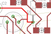
I got the schema for the "sweetheart led" board online and drew it in eagle. I then placed the components and attempted autoroute. The most this could drew was 94%. After hours of trying to make eagle route it for me, I decided to draw the lines to see it worked just once.

For some reason, eagle thinks I haven't got the connections right? I can't understand this at all! I copied the connections DIRECTLY from the board.

Below are screenshots, and I have attached the board and schema from eagle in a zip file.

I am sure the error is mine but I can't tell what it is!!! If anyone can spare a minute to help me I would massively appreciate it.


THANKS!

myboard.png
heart.png

PDF from velleman detailing schema
View attachment sweetheart.pdf

Zip file
View attachment Board.zip
 
Eagle is cool once you understand all. And there is a hell of a lot you can do with it.
I have been using it for years and it now and and again trips me up too. Still the best out there.

My suggestion: Get a member here to help you out (not me). You will surprise your G/F with something really beautiful.

Try please.....
 
If you still have air wires then either the schematic or the layout is wrong. Match them up and figure out why.

You can also hit the ratsnest button. Sometime the airwires get confused and just stick to places they shouldn't.
 
Unfortunately I tried that ...which is why I know I got a problem :(

I got the schema from velleman and the board is exactly the same layout as the actual board I own. Any other ideas?


Would eagle tell me if I connected something that I shouldn't?
 
It is asking me for resistor values... surely this doesn't make a difference? Or does it?
 
You get a little 'bing' sound and the trace locks on when you connect to the right spot. Unfortunately Eagle has no problem with you putting traces on the same layer over each other. That kind of thing is only found with a Design Rules Check.

I downloaded your files. I didn't realize you posted them.

I don't know what more to tell you. Either the layout is wrong or the schematic is wrong. Are you sure the PCB doesn't have any top traces or jumpers? Using the little 'eye' icon on the toolbar helps with this kind of thing as it will highlight a full net on both the schematic and the board layout so you can see where everything is.
 
Last edited:
I don't know what more to tell you. Either the layout is wrong or the schematic is wrong. Are you sure the PCB doesn't have any top traces or jumpers? Using the little 'eye' icon on the toolbar helps with this kind of thing as it will highlight a full net on both the schematic and the board layout so you can see where everything is.

Awesome. This sounds just the thing. Just click on a couple of items and it maps them nicely. This should be a quick means of identifying the problem!

THANKS!!!!! :)
 
Yes, I used the show tool and clicked around a bit and you definitely have nets that are connected to traces that they should not be.
 
Yes, I used the show tool and clicked around a bit and you definitely have nets that are connected to traces that they should not be.

I copied it perfectly! When I hold the board up to the light I can see there are no other traces/vias.
 
I did a show on one of the traces. You are connecting nets that don't connect in the schematic.

I'm thinking you've placed components differently than they are on the reference board. You also have an issue since you are using the copper on the top of the board (red) and your components are also placed on the top of the board, so your transistor pins are reversed.
 

Attachments

  • eagle-question.png
    eagle-question.png
    13 KB · Views: 154
Hi beakie,

the most important thing with Eagle (and any other PCB editor) is connecting components properly in the schematic.

Changing grid size you shoud be aware of changing inches and fractions thereof, e.g. 1/10, 1/20, 1/40 etc.

Changing grid size at odd numbers you might not have connected nets as you intended. Nets look like being connected, but when highlighting them they stop in the middle of nowhere.

When changing to "board" Eagle only knows nets between correctly connected pins! Missing one pin can ruin the work of eight to ten hours of schematic work not leading to the expected results, especially if there are lots of components to be connected.

My advise for the future: Use the ULP "NETLIST" to check your work.

Take the time and compare the Eagle connections with the intended ones to make sure the schematic is 100% alright.

Changing to "board" the air wires will never be wrong!

Creating a board with more than 80 ICs and the size of 420X260mm you'll know what I talked about.

Once again: electronics work require precision from beginning to the final board design.

Regards

Boncuk
 
Last edited:
Hey,
I looked over your board files and the schematic looks fines. However, the board routing is a mess. Besides the unrouted airwires you also have several short circuits if you left the routing as is.
Personally, I have never had much luck using the autorouter and I just don't like the looks of it ( not that it maters much, just my personal preference ). You should be able to manually route this board without too much trouble.
Be sure you run the ERC and DRC to find those problem areas.

Good Luck!
 
try this

Since I had the file open I relocated a few resistors and rotated a few others and got the complete autoroute. You should check this completely before you use it. Better yet.. see what I did and try it yourself.. best way to learn is by doing.

Regards!
 

Attachments

  • Board_a.zip
    149 KB · Views: 122
Since I had the file open I relocated a few resistors and rotated a few others and got the complete autoroute. You should check this completely before you use it. Better yet.. see what I did and try it yourself.. best way to learn is by doing.

Regards!

That's impressive, sir! Thank you. I totally agree about learning by doing. Hey that's why I am playing with eagle in the first place :)

I have actually just been rearranging the components. Flipped the board layout around, my transistors were the wrong way round.

I got a photo of the board, made it a 2 colour bitmap, made it a package and used it to draw the lines backwards :D

I am now 98% complete! Can't work out why the last 2% won't play ball though.

This is the problem bit. Eagle is suggesting a different connection to the board? Every other connection maps except one????? Also, if I made the connections it suggested, I would connect the cathode and anode together? No?

x.png

Here are the eagle files.

View attachment Board2.zip (Zip of the board (v2) and schema)


Cheers everyone for taking the time to look, I really appreciate your efforts
 
Last edited:
This is how eagle wants me to connect the led. Clearly these connections don't make sense. Why is it doing this?

d.png

This is how I believe it should be connected. But eagle is still expecting more lines...

e.png
 
Last edited:
Woooooooooo! 100%!!!!


There was a small dot of connection around the led. Even though I moved the led a thousand times to look for it, i didnt see it until i accidentally clicked on that exact dot.

Thanks to everyone for all your help. I really appreciate your time.

Cheers. Bedtime.
 
If you are etching this yourself, you can print it directly from Eagle. Since you used the top copper, you need to use the mirror selection when printing.
 
Status
Not open for further replies.

Latest threads

New Articles From Microcontroller Tips

Back
Top