Continue to Site

Welcome to our site!

Electro Tech is an online community (with over 170,000 members) who enjoy talking about and building electronic circuits, projects and gadgets. To participate you need to register. Registration is free. Click here to register now.

  • Welcome to our site! Electro Tech is an online community (with over 170,000 members) who enjoy talking about and building electronic circuits, projects and gadgets. To participate you need to register. Registration is free. Click here to register now.

Eagle cad 74XX library

Status
Not open for further replies.

Mikebits

Well-Known Member
Another question with eagle.
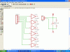
When I pull up a standard logic device like a 74LS00 gate, the VCC pin is not shown. If I want this to be connected to a particular net name and have it shown, how do I go about this? I did find the invoke command which calls up the pwr and gnd pins but this looks ugly, is there a better way?

Thanks
 
Eagle thinks it is best to make parts where GND and VCC are all connected together.
I often work on boards where there are 3 grounds and 10 supplies. I can't have Eagle connecting up the supply pins for me.
1. There is a button called "INVOKE". Press it and then click on a part. It may say there are 6 inverters used on page one and a power not used on any page. Use this to get the power portion of the part on your sch.
2. In cases of analog parts where there is no reason to connect (GND) to ground and (+) to VCC, I often go edit the liberary and rename the "power pins" to "IO pins". This way I can connect the supply pins to -12V and +15V.
 
Thanks all. I used the invoke function, but I think it looks bad. Oh well it is a free package, can't complain.
 
Hi Mike,

here is a small circuit with the power pins of the IC invoked.

Notice the ERC warning. Instead of connecting pin14 to VCC I used +5V. Pin7 is connected to ground as the pin name suggests. Connecting it to VSS you'll get one more warning.

Please note that the DRC also warns about unconnected output pins.

Regards

Boncuk
 

Attachments

  • CIRCUIT.gif
    CIRCUIT.gif
    34.9 KB · Views: 939
  • DRC.gif
    DRC.gif
    21.7 KB · Views: 479
  • BOARD.gif
    BOARD.gif
    45.4 KB · Views: 623
Last edited:
I often go edit the liberary and rename the "power pins" to "IO pins". This way I can connect the supply pins to -12V and +15V.

Hi Ron,

you might connect the power pins wherever you want. All you get is a warning when performing a ERC.

Refer to the post please.

Regards

Boncuk
 
Status
Not open for further replies.

New Articles From Microcontroller Tips

Back
Top