lo9999s
New Member
Hello there
I am working on a project which involves the development of a pressure sensor matrix capable of pressure mapping the force applied on a patient by a medical instrument.
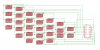
The active measuring area consists of a matrix of 28 interdigitated electrodes on a PCB.
I am trying to design this, but I am having some trouble with the autorouting.
When i press the function it stays in 0% and doesnt seem to even start the process.
I played around a little with the design rules, but I am pretty new to this whole world and I am sure my problem is somewhere there, I just cannot seem to find it
Unfortunately it doesnt let me attach the schmematic file here, but if anyone has any idea what it could be and has the time to help me out, please contact me and I will send you the file somewhere else, so you can see my design for yourself.
I hope I am making sense here, and I really hope one of you out there with more experience can help me out!
Thanks a lot for your time
I am working on a project which involves the development of a pressure sensor matrix capable of pressure mapping the force applied on a patient by a medical instrument.
The active measuring area consists of a matrix of 28 interdigitated electrodes on a PCB.
I am trying to design this, but I am having some trouble with the autorouting.
When i press the function it stays in 0% and doesnt seem to even start the process.
I played around a little with the design rules, but I am pretty new to this whole world and I am sure my problem is somewhere there, I just cannot seem to find it
Unfortunately it doesnt let me attach the schmematic file here, but if anyone has any idea what it could be and has the time to help me out, please contact me and I will send you the file somewhere else, so you can see my design for yourself.
I hope I am making sense here, and I really hope one of you out there with more experience can help me out!
Thanks a lot for your time