Electro Tech is an online community (with over 170,000 members) who enjoy talking about and building electronic circuits, projects and gadgets. To participate you need to register. Registration is free. Click here to register now.
Welcome to our site! Electro Tech is an online community (with over 170,000 members) who enjoy talking about and building electronic circuits, projects and gadgets. To participate you need to register. Registration is free. Click here to register now.
Hi..
I`m trying to build a LED in to a E27 220V. housing. My big Q is, What do I need to drop the current to 12V. the LED is using 1,3Watt ?
and the 220V. is AC, and I need 12V.DC
??
Hi..
I`m trying to build a LED in to a E27 220V. housing. My big Q is, What do I need to drop the current to 12V. the LED is using 1,3Watt ?
and the 220V. is AC, and I need 12V.DC
??
What you need to drop the voltage from 220V to 12V is a transformer. 1.3 W for the LED sounds a little high. The power dissapated by the LED will be the product of the current flowing through it and the voltage drop across it. You can obtain the forward voltage of the LED from its data sheet but it will probably be between 2.5 - 3.5 V. The current flowing through it will be dictated by a current limiting resistor that you must place in series with it. The current can be calculated by using V=IR and once again you should obtain the appropriate value from the data sheet. If you're uncertain start around 15 mA and work your way up until you reach the desired brightness. Also, you don't need 12 VDC. You can use the 12VAC from the transformer. The LED will only be lit half the time but it will be blinking so fast it will be unoticable.
without knowing what the operating voltage and current of the LED is, it's a little hard to give definitive answers. Basically, to drive an LED from mains, you will want a converter: maybe a transformer (very big), or a SMPS (small, efficient & output voltage/current adjustable). You can get a 2.5W SMPS for under $3, and with a little tinkering you'll be able to get it to output a constant current to the LED (and maybe even get it to fit in the lamp housing).
In fact, there are some integrated solutions in the market. But I don't see how they fit a SMPS with caps, IGBTs, MOSFETs and all in a tiny housing.
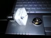
My advice: buy one and disassemble it. There are LED lightbulbs just like the one you're trying to make for sale on e-bay for $14.
Reverse engineering is still the best way to learn practical consumer oriented electronics.
If you're brave enough to continue without the less glamourous but much easier reverse engineering way, I think there are ICs that does that already, and are intended for LED lighting.
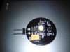
I googled the components used in the circuit you showed and found the datasheet of the buck converter that drives the LED. It's the PT4115.
**broken link removed**
In this datasheet, at page 15, figure 1, you can see the schematic of the bulb's circuit.
The strange thing is that the recommended maximum input voltage the PT4115 takes is 30 V (after the bridge rectifier), but the datasheet doesn't specify if it's RMS or peak voltage. Even if we assume it's referring to the RMS voltage (meaning that it could hold a voltage as high as 42.4V...), something is still missing.
Look inside the bulb for a little transformer. There may be one 220/18 transformer there. Or else the circuit wouldn't work (I think...). If there isn't, I don't know how it works...
And using the LM7812 is not a good idea. It's a linear series regulator, so it's not too power efficient. You can use it to build a smps, yes, but there are better integrated solutions. Besides, you would still need a transformer as the LM78xx series doesn't work at high voltages (higher than 40V).
it is at this point where I wish I had an electrician training approval ..
So what your telling me, that theres no easy / simple way to make it work ?
When I get home from the Christmas holidays , I will look for the 220/18 transformer..
Look inside the bulb for a little transformer. There may be one 220/18 transformer there. Or else the circuit wouldn't work (I think...). If there isn't, I don't know how it works..
You can wind your own transformer on a ferrite E-core (easy) or torroid (painful), and it can be very small.
If you don't require the LED module to be isolated from the mains: you can get away with only 2 windings (take another diode-cap feed off the secondary winding) and you can use a transistor (instead of an optocoupler) to provide feedback to the controller IC.
There's a drawing on page 13 of the datasheet with an example of number of turns etc. As your power requirements are less than those in the example so you would wind a few more turns on the primary.
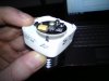
The IKEA led light that you took apart probably uses a capacitor for current limiting. It would have to be a 400 V capacitor and I can't see it in the pictures, but I can't see how else it would work. It could be inside the screw part of the light.
The component labeled S489A is a voltage supressor, which is really a high voltage zener diode. The 400 V capacitor lets a few mA through, limited in voltage by the "S489A" to somewhere around 40 V and the PT4115 and its associated inductor etc increases that current, while reducing the voltage, to drive the LED.
If they had just limited the current with a 400 V capacitor, the light would have taken more current and had a very poor power factor. The capacitor would have been very large. The design that they have used supplies 10 - 20 times as much current to the LED as is taken from the mains, but doesn't need expensive components.
Little flyback transformers like you are looking at on the FSQ0170RNA data sheet are extremely difficult to get right, and make for a lot more complication. I have tried and failed to wind them correctly. The problem getting the stray inductance low enough. As the current in the primary coil is interrupted, any stray inductance in the secondary will cause a voltage spike. If there is also stray inductance in the primary, that is at all linked to the auxiliary winding, there will be a big spike on the auxiliary winding. This means the auxiliary voltage rises too high and shuts down the FSQ0170RNA. You can see that transformer construction is critical from the fact that they have had to split the primary winding in two, and wind half either side of the secondary.
I hope I don't sound too condescending, but I don't expect you to understand the previous paragraph. If you don't understand it, you certainly shouldn't be thinking about making a flyback transformer. I suggest you look more carefully at the IKEA lamp which is much simpler.
The IKEA led light that you took apart probably uses a capacitor for current limiting. It would have to be a 400 V capacitor and I can't see it in the pictures, but I can't see how else it would work. It could be inside the screw part of the light.
The component labeled S489A is a voltage supressor, which is really a high voltage zener diode.
I think you should read up above (caster.cp's post regarding the PT4115). The LED board is a low voltage buck converter. The S489A would be a schottkey diode. The IKEA housing is taken from a CFL; the OP seems to want to make a converter to sit in the IKEA CFL housing to make 12VDC to power the LED converter board.
Little flyback transformers like you are looking at on the FSQ0170RNA data sheet are extremely difficult to get right, and make for a lot more complication. I have tried and failed to wind them correctly. The problem getting the stray inductance low enough. As the current in the primary coil is interrupted, any stray inductance in the secondary will cause a voltage spike. If there is also stray inductance in the primary, that is at all linked to the auxiliary winding, there will be a big spike on the auxiliary winding. This means the auxiliary voltage rises too high and shuts down the FSQ0170RNA.
While I'm yet to use one of these converters (I just ordered a couple so I'll see if I can have any better luck), I can imagine these spikes can be removed with a well placed snubber (e.g. on the primary coil - possibly with a flyback diode & RC or C+Zener). I've also seen a series resistor placed on the controller VCC transformer winding, probably to reduce the coupled spike you mentioned.
This site uses cookies to help personalise content, tailor your experience and to keep you logged in if you register.
By continuing to use this site, you are consenting to our use of cookies.