Continue to Site

Welcome to our site!

Electro Tech is an online community (with over 170,000 members) who enjoy talking about and building electronic circuits, projects and gadgets. To participate you need to register. Registration is free. Click here to register now.

  • Welcome to our site! Electro Tech is an online community (with over 170,000 members) who enjoy talking about and building electronic circuits, projects and gadgets. To participate you need to register. Registration is free. Click here to register now.

Dual stage Temp Switch using LM358N Op Amp.

Status
Not open for further replies.

pigman

New Member
Hey,
I just did a basic dual stage temp switch circuit using the LM358N that I have been playing around with, I am yet to test this circuit but thought I would run it past you guru's and get your opinion on if it will work or if I need to adjust anything?

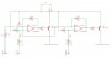
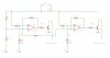
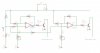
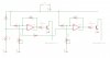
Basically it uses the same 10k thermistor on both non-inverting inputs A and B and uses two trim pots to set A and B's on point allowing the circuit to switch say two fans at different temps or something like that.

Let me know your thoughts.

Cheers
 

Attachments

  • dual-stage-temp-switch.jpg
    dual-stage-temp-switch.jpg
    63.1 KB · Views: 414
hi,
The problem with the LM358 OPA, is that the Vout max is 12V-1.5V =10.5V, this means the transistors will never turn off,as the Vbe will be a Vmin of ~1.5V relative.
Have not looked thru the rest of the circuit.

EDIT,
I would also add a 10K in series with each OPA input thats connected to the 10K/thermistor junction, else the hysteresis of each stage will cause some interaction.
 
Last edited:
I see the interactions of the two stages. I would move the TR and 10K resistor to the (-) inputs of the LM358s. Then move the pots to the (+) inputs. This will reverse the logic.
 
ron, by reverse the logic do you mean when the threshold of each is reached the input will go high instead of low? IE is the attached suitable?
ericgibbs, I added the 10k in series between A and B is this enough?
 

Attachments

  • dual-stage-temp-switch-v2.jpg
    dual-stage-temp-switch-v2.jpg
    64.6 KB · Views: 378
ron, by reverse the logic do you mean when the threshold of each is reached the input will go high instead of low? IE is the attached suitable?
ericgibbs, I added the 10k in series between A and B is this enough?

hi,
As you are now using NPN transistors that will invert the sense, do what Ron suggests and invert the drive to the Comps, this will restore the the circuit sensing..
 
ericgibbs, I have inverted the drive to the comps in the latest version above. and at the same time changed to NPN. Is it correct that it will switch the NPN's on when the temp threshold of each is reached individually?
 
ericgibbs, I have inverted the drive to the comps in the latest version above. and at the same time changed to NPN. Is it correct that it will switch the NPN's on when the temp threshold of each is reached individually?

hi,
You have misread what Ron has said, you have just crossed over the inputs!
So the hysteresis is the wrong sense.

EDIT:
Look at this option.
 

Attachments

  • dual-stage-temp-switch-v3.jpg
    dual-stage-temp-switch-v3.jpg
    51.9 KB · Views: 551
Last edited:
ohh, ok my bad. So the Hysteresis should be back on the + of each input? See attached.

EDIT - Ron, thanks for that, so now the outputs of each A and B will switch on the NPN's as they reach their corresponding temperature?
 

Attachments

  • dual-stage-temp-switch-v3.jpg
    dual-stage-temp-switch-v3.jpg
    63.7 KB · Views: 199
Last edited:
Post #4: Move R3, R6 back to the + input. Positive feedback
Remove R8 ---short out---
Your load is now from +12V to C of the transistors.
 
AWESOME! So this should work a treat as a little dual stage thermal switch?
On another note, does anyone have the formula/a table of resistance v temperature of a standard 10k NTC Thermistor handy?
 
More information! A search at DigiKey shows 400 different 10k NTC parts. What do you have?
 
The data gives you the resistance at 25C. +/- a little.

Depending on the type there is a number like -3%/C. Maybe you should test your sensor using room temp and boiling water.
 
Status
Not open for further replies.

Latest threads

New Articles From Microcontroller Tips

Back
Top