Continue to Site

Welcome to our site!

Electro Tech is an online community (with over 170,000 members) who enjoy talking about and building electronic circuits, projects and gadgets. To participate you need to register. Registration is free. Click here to register now.

  • Welcome to our site! Electro Tech is an online community (with over 170,000 members) who enjoy talking about and building electronic circuits, projects and gadgets. To participate you need to register. Registration is free. Click here to register now.

dual polarity power supply

Status
Not open for further replies.

Wond3rboy

Member
i have made a dual power supply i dont understand why i dont get enough voltage at the output??
 

Attachments

  • powersupply.JPG
    powersupply.JPG
    51.4 KB · Views: 377
i have made a dual power supply i dont understand why i dont get enough voltage at the output??

hi,
The smoothing caps are much too low in value.

Whats the transformer secondary rated at [Volts= ??] and what voltage do you get.?
 
The input voltage and frequency is also incorrect.

The mains in the US is 60Hz and most simulation programs accept peak voltages, not RMS voltages so you should enter 120√2 = 169.7V rather than 120V.
 
If you get mains hum in Pakistan they you will be slowly shaken to death.
 
But at least you won't be able to hear the fundermental, just the +20th harmonic which won't be very loud.

Imagine how large the 1F filtering capacitors and power transformer would be.
 
No. The power transformers in Pakistan must be
HUGE.:D

thanks for enlightening us about this point!!
i tried increasing the capacitor values but than the output voltage decreases.

about the freq this is just done on the simulator which for some reason gives an error when operating with high freq.
 
thanks for enlightening us about this point!!
i tried increasing the capacitor values but than the output voltage decreases.

about the freq this is just done on the simulator which for some reason gives an error when operating with high freq.


hi,
You must simulate with the correct frequency. 50Hz or 60Hz
Using 1Hz will not work correctly.
 
now it gives a output of 4v on each side but when i increase the capacitor values than it again gives an error.why is that happening?
 
now it gives a output of 4v on each side but when i increase the capacitor values than it again gives an error.why is that happening?

hi,
I assume we are talking about a simulated power supply.???

What secondary voltage have you set the transformer to.?

Is the simulation allowing 50/60Hz for the Vac input.?

What 'error' does the simulator report.??
 
I wouldn't recommend Electronics Workbench, it's very flakey.

I managed to get it to work after a lot of playing around.

Read the "Time Step Too Small" error section of the help file.

Use LTSpice, it's free (as in price) and much better too.

It doesn't come with a centre tapped transformer model but I'm sure you can find one on the Internet.
 

Attachments

  • bipolar psu.zip
    8.1 KB · Views: 164
yeh i norm,ally sue ltspice but didnt use it because of the unavailibility of the centre tapped transformer

hi,
Just for simulation, why dont you configure [ltspice] using two identical transformers, with their own FWB [full wave bridge]?

One with the -V as ground [0v] and the other with +V to ground.. link the grounds together.
 
With LTspice, you can use one of the circuits shown below.
 

Attachments

  • transformer driven rectifier.PNG
    transformer driven rectifier.PNG
    16.7 KB · Views: 213
  • transformer driven rectifier.asc
    4.1 KB · Views: 150
How did you make the transformer model?
 
How did you make the transformer model?
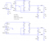
It's 3 inductors. K1 specifies the coefficient of coupling. Look up "mutual inductance" in the help section. Also look up "transformer model". I used K=1, which would be an ideal transformer, but in the real world, it will always be somewhat less. K=0 is no coupling.
I chose the primary inductance to be 10 Henries, just to keep the no-load primary current low. Practical values may be lower.
My inductors have series resistance incorporated in them, but you have to load the file into LTspice and right-click on them to see the values. I think I arbitrarily made them all 1 ohm.
As you know, the inductance is proportional to the square of the number of turns, and the voltage ratio is proportional to the turns ratio, so a 100:1 inductance ratio yields a 10:1 voltage ratio.
 
Last edited:
Status
Not open for further replies.

New Articles From Microcontroller Tips

Back
Top