Continue to Site

Welcome to our site!

Electro Tech is an online community (with over 170,000 members) who enjoy talking about and building electronic circuits, projects and gadgets. To participate you need to register. Registration is free. Click here to register now.

  • Welcome to our site! Electro Tech is an online community (with over 170,000 members) who enjoy talking about and building electronic circuits, projects and gadgets. To participate you need to register. Registration is free. Click here to register now.

Dual monostable mode 555 timer with same button reset!

Status
Not open for further replies.

rokz_2005

New Member
Hey guys my first thread :D

My first project which I'm learning basic electrics with.
I'm still awaiting my delivery for parts hence I cant test this.

plus I'm sure you guys will be able to tell me where I'm going wrong by just looking at it instead of me frying it then realising 'oh yea'

--------------
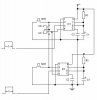
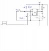
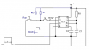
This is the final schematics for having a dual timed monostable set up with either button to reset the 555 while on a monostable run.

in this set up the output can be motor, LED's or a bleeper.

Can you guys tell me if I've gone wrong anywhere or will this work.

Thanks
 

Attachments

  • 555 n spno.jpg
    555 n spno.jpg
    15 KB · Views: 792
Welcome to the forums!

I am not sure where you are going with this. You have a 555 timer configured as a monostable (one shot) multivibrator. OK, that is a given. The output pulse on pin 3 will have a duration determined by the RC time constant set up by R1 and C1 (T = 1.1 R C). You trigger the circuit by applying a low to the trigger input on pin 2, when you trigger with your push button you get your pulse out on pin 3. Pin 4 (Reset) in circuits like this is tied to Vcc as there is no need to reset the timer. I don't understand the reset scheme?

Also, the output on pin 3 of a standard 555 timer IC can drive about 200 mA of current, though I suggest you remain below that. If your lamp, motor, or other load requires higher current you would use a transistor to drive the load.

Ron
 
Last edited:
Its for an Led project.
Imagine the output are Green and Red.
When I press switch 1 the green LED lights up for 10 seconds
when I press switch 2 the Red LED lights up for 10 seconds
Because it has a timer power output if I wanted to reset the circuit manually I would have to basically cut the power to PIN 4 and that's exactly what this diagram shows EXCEPT that the reset and switch will conflict. Therefore I wanted to know how to add a 1 second delay to each switch. I'm still learning about electronic circuits.

Reloadron - I just wanted to find a way of manually resetting the output (without letting the time cycle finish) e.g stop Red/Green LED with either switch then press the switch again to start the 10 second run

Thanks for your comments
 
Last edited:
hi,
There are a number of problems with your posted circuit.

Pin #2, the Trigger has to be connected to +V , via a resistor, say 4k7.
Each pin2 must have its own resistor to +V

What is the purpose of the change over switch and diodes.???

The easist solution to Reset either 555 mono, would be to connect pin 4 to +V via a 4k7 resistor and use a push switch to pull pin 4 to 0V.. Each pin4 must have its own resistor and push switch
 
The change over switch (SPNO relay) is to stop the any power going into PIN4 which resets the timer no matter what state its in (In this case I would like to stop the monostable output using wither of the button)
I guess I put the diode in there so that the power does not run from the tops circuit to the bottom (to create a one way current flow into the relay only) If I'm correct, without the diode the switch could potentially set both of the 555's off? I think i may have forgotten to add a few more components like resistors and grounding the 'NO' terminal.

Sorry I am still learning, It's only been a week :p please do advise me
 
Last edited:
hi,
There is nothing to be sorry about.:)

Look at this image, it shows one 555, but both circuits will be identical.

One switch for Run, one for Reset.

OK.?
 

Attachments

  • 555 n spno.jpg
    555 n spno.jpg
    11.2 KB · Views: 335
Hi, thanks for that, that does look good.
I wanted to use the same switch for reset hence the relay. I am still learning the symbol, so what have you put in the 'reset' part. Which component would that be.

Lets use your circuit design so it will be easier for me to understand. Lets pretend for a moment that the circuit has one switch and one LED.
I wanted to add a RC Ramp on the switch (I believe) to add a delay of 1sec to start the monostable run (I don't know know how to do this yet - maybe someone can help :p)
In theory When I press and hold the switch the RC ramp will be charging.
After the charge the LED will come on for 10sec BUT I wanted to use the same switch to stop that 10 second run manually or when I chose to.
At the same time I would like PIN4 to go low so the timer goes into reset.
I don't think the anything will conflict because in order to reset I just gotta press the switch it and not hold it for the RC ramp to charge up.
The main problem is that because PIN4 has to be connected to power I put a relay in so that when the switch is pressed the power is cut from PIN 4 only, forcing it to reset But the power will flow into the Rc ramp

Does that make any sense.


I'll break it down because I'm not even sure what I am saying lol

Switch has a 1 second delay to trigger
while in monostable mode press the switch again to force it out of monostable mode

I think I'm repeating myself too many times. I have to apologise for that. I can see it working in my head but I need expert advice
 
Rc ramp added according to the site I copied it from it will give an approximate 1second delay?
so the Rc will only go to trigger and won't affect PIN 4
 

Attachments

  • with rc.png
    with rc.png
    13.1 KB · Views: 223
Rc ramp added according to the site I copied it from it will give an approximate 1second delay?
so the Rc will only go to trigger and won't affect PIN 4

hi,
The circuit as copied from the linked site will not work as you have drawn it.

Can you post a link to the site where you copied it from.?
 
hi,
This circuit will do want you want.

1. Press Switch , resets the 555
2. Release Switch, 555 timer starts
3. Pressing again BEFORE time out period ends will reset the 555
4. Normal time out period, if Switch not pressed during timing.

Adjust value of R1 timing resistor to get the required mono timing period.
 

Attachments

  • AAesp05.gif
    AAesp05.gif
    42.8 KB · Views: 271
Last edited:
OMW! electrics is harder then I thought.
Wow.... 2 questions
Can I connect this to a duplicate circuit where both switches can reset each other?
The input is 12v DC, what are the new resistors?


Thanks ( I need to pop down to the shops again to but some more components :p)
 
Last edited:
OMW! electrics is harder then I thought.
Wow.... 2 questions
Can I connect this to a duplicate circuit where both switches can reset each other?
what does S1 stand for ?

Thanks ( I need to pop down to the shops again to but some more components :p)

S1 is your push switch,

Not sure what this means.
Can I connect this to a duplicate circuit where both switches can reset each other?
 
S1 is your push switch,
I figured that after feeling silly.
So I changed that to if the input was 12v dc (that's the battery pack that I'm using)
Which resistor values do I have to change and what to. Can i not just add a resistor between the power to bring the total V input to 9v?


Not sure what this means.
My original idea was that I have two of these circuits. one operates a green LED and the other a red LED. Each with their own respective switch. But what I wanted to do was to use either of the switch to cancel the monostable output on either LED's.
 
My original idea was that I have two of these circuits. one operates a green LED and the other a red LED. Each with their own respective switch. But what I wanted to do was to use either of the switch to cancel the monostable output on either LED's.

The two circuits would be identical, I designed the Reset to suit your original idea.
 
Cool
What I mean is that if I connect PIN 4 together on both circuits like the one in the pic. Would I be able to reset either circuit with either button?

Thanks I just need to confirm then Im off to the hobby shops :D excited :):)

In regards to the 12v input. Can I still use the same values for the resistors and capacitor or do I have to change em?
 

Attachments

  • One button to rTwin circuit either reset.gif
    One button to rTwin circuit either reset.gif
    26.3 KB · Views: 259
hi,
If just connect the two circuits together as you have shown, every time you push either switch, both timers will Reset, when either switch is released both will start running.

Look at this option.

I dont understand why you dont want to use a separate Start/ Reset for each circuit.??
 

Attachments

  • AAesp01.gif
    AAesp01.gif
    19.7 KB · Views: 228
Last edited:
Just to make sure. C3 will cause a delay to the start up of the timer by 1 second correct??

ericgibbs - Thanks for that. I mean having two totally separate circuits is not a big deal. I just like to create something just the way I see/want it. It creates a challenge sometimes which I enjoy.
Does your circuit complete my dream :p? Thanks
 
What I wanted was I press and hold the switch for 1second
the monostable starts and runs for 10seconds
If for any reason I wanted to stop the monostable run, I would press the same button again.
I want the reset to be instant but the normal out pur to have the 1 sec delay.

That's what I am trying to make.

Can I not just add an RC ramp to trigger??

And does it matter which watts resistor I use?
 
Last edited:
Status
Not open for further replies.

New Articles From Microcontroller Tips

Back
Top