Continue to Site

Welcome to our site!

Electro Tech is an online community (with over 170,000 members) who enjoy talking about and building electronic circuits, projects and gadgets. To participate you need to register. Registration is free. Click here to register now.

  • Welcome to our site! Electro Tech is an online community (with over 170,000 members) who enjoy talking about and building electronic circuits, projects and gadgets. To participate you need to register. Registration is free. Click here to register now.

dual-4 bit binary counter

Status
Not open for further replies.

holdfast9

New Member
helo everyone..:)
can anyone explain me what is dual 4-bit binary counter..what it is use for? where we can apply it?

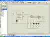
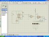
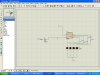
my teacher ask me to design a circuit using 555, 74LS11, & 74LS393..

the circuit show us how dual 4 bit binary counter works by seeing the LED..

I try to design it using the ISIS PROTEUS software..but it doesn't work..can anyone help me?
 

Attachments

  • dual 4-bit binary counter.JPG
    dual 4-bit binary counter.JPG
    247.3 KB · Views: 3,105
A dual 4-bit binary counter.

Dual means that there are two(2) binary counters each of which is four bits long.

4-bits means that each of the two counters has 4 binary digits or bits. Each bit can take only the values zero(0) or one(1)

binary means the the counters inputs and outputs are represented in the binary or base two number system.

The 4-bit binary counter has the following set of outputs:

{0000,0001,0010,0011,0100,0101,0110,0111,1000,1001,1010,1011,1100,1101,1110,1111}

Each time there is a clock pulse the counter goes to the next state. Some counters go through the sequence in the forward direction and they are called up counters. Some counters go through the sequence in the backward direction and they are called down counters. Some counters can do both depending on the state of a control input.

What are they used for? Everything. IMHO it is a dead heat between counters and shift registers for the title of most useful part.
 
In the attached diagram you have unused inputs of an AND gate connected to GND - they should be connected to +V. You could also just connect them all together and to the 555.

Mike.
 
What's the purpose of that NAND gate?

All it's doing is acting as a buffer and the 555 is more than capable of driving the counter so it can be omitted altogether.
 
Pommie said:
In the attached diagram you have unused inputs of an AND gate connected to GND - they should be connected to +V. You could also just connect them all together and to the 555.

Mike.


ok i connect all the input of AND gate to the 555 & i do some modify to circuit..


the LED is on..and its start counter..from 0000-1111

1st and 2nd cycle it count properly..but when the 3rd cycle the simulation is failed...why?

thanx for ur advice...i appericiate it..:)
 

Attachments

  • 4 bit binary counter.JPG
    4 bit binary counter.JPG
    248.2 KB · Views: 1,522
holdfast9 said:
ok i connect all the input of AND gate to the 555 & i do some modify to circuit..

You don't need the AND gate, read my post above.
 
ok..now i want to change the 555 to crystal 80Mhz..& the 74LS393 to 74HC393..because i am doing fast circuitry..

in the ISIS how to connect the crystal to input 74HC393?

is my circuit correct? i run the simulation..it doesn't work..why?:(
 

Attachments

  • BIN XTAL.JPG
    BIN XTAL.JPG
    244 KB · Views: 374
A crystal will not work as you have connected it.

Electrically a crystal behaves like an LC tuned circuit. You will need some other components before it will oscillate.

However, a crystal oscillator is a complete circuit and crystal in one metal (usually) package. It just needs 5v and out comes an 80Mhz or whatever frequency square wave.

JimB
 
Because all you've done is added a crystal! You need to build a propper little crystal oscillator consisting of an amplifier with the crystal in the feedback network. At 80MHz is so fast you won't be able to see the LEDs flash, in fact LEDs aren't even fast enough to turn on and off at that speed.

Use a CD4060 and a 32768kHz crystal to get 2Hz, then use that to drive your counter with.
 
Hero999 said:
Because all you've done is added a crystal! You need to build a propper little crystal oscillator consisting of an amplifier with the crystal in the feedback network. At 80MHz is so fast you won't be able to see the LEDs flash, in fact LEDs aren't even fast enough to turn on and off at that speed.

Use a CD4060 and a 32768kHz crystal to get 2Hz, then use that to drive your counter with.


oic...i still dont know how to built that circuit:confused: ...what & where source should i refer to..to understand how to built a proper crystal oscillator..
 
Papabravo said:
A dual 4-bit binary counter.

Dual means that there are two(2) binary counters each of which is four bits long.

4-bits means that each of the two counters has 4 binary digits or bits. Each bit can take only the values zero(0) or one(1)

binary means the the counters inputs and outputs are represented in the binary or base two number system.

The 4-bit binary counter has the following set of outputs:

{0000,0001,0010,0011,0100,0101,0110,0111,1000,1001,1010,1011,1100,1101,1110,1111}

Each time there is a clock pulse the counter goes to the next state. Some counters go through the sequence in the forward direction and they are called up counters. Some counters go through the sequence in the backward direction and they are called down counters. Some counters can do both depending on the state of a control input.

What are they used for? Everything. IMHO it is a dead heat between counters and shift registers for the title of most useful part.

Thats an excellent explanation. Well done i could have said it better myself :)
 
Status
Not open for further replies.

Latest threads

New Articles From Microcontroller Tips

Back
Top