AtomSoft
Well-Known Member
I am using a DS1337 (Not the C version) and every time it the minutes reach over 39 (so 40) it changes to 00. I know its the chip and not my code because i never write to the DS1337 unless its to set time which is done by buttons. Any thoughts? Faulty chip perhaps?
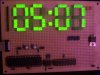
So my issue is i set the time to 7:45 and it changes itself to 7:05.
If i set to 7:38 its ok. Works fine untill it hits 39 where it jitters then 40 changes to 00. Any thoughts?
Here is my code.. (sorry not enough comments)
So my issue is i set the time to 7:45 and it changes itself to 7:05.
If i set to 7:38 its ok. Works fine untill it hits 39 where it jitters then 40 changes to 00. Any thoughts?
Here is my code.. (sorry not enough comments)
Code:
#include <p18f452.h>
#include <stdio.h>
#include "delay.h"
#include <spi.h>
//#include "sw_i2c.h"

#pragma config WDT = OFF, LVP = OFF, OSC = HS

#define SDA_PORT PORTBbits.RB0
#define SDA LATBbits.LATB0
#define SDA_TRIS TRISBbits.TRISB0
#define SCL LATBbits.LATB1

#define CS LATDbits.LATD0
#define Dots LATDbits.LATD1

#define dwnBtn PORTBbits.RB3
#define upBtn PORTBbits.RB4
#define entBtn PORTBbits.RB5

char slave_r = 0b11010001;
char slave_w = 0b11010000;

//TIME
char sec_h, sec_l;
char min_h, min_l;
char hour_h, hour_l;
char t_temp;

//Set Time
char setBtn;

void main(void);
void Init(void);
void WriteWord(char address,char data);
unsigned char WriteSPI(unsigned char data);
char rtc_write(char offset, char data);
char rtc_read(char offset);
void i2c_byte(char addr);
void i2c_start(void);
void i2c_ack(void);
char i2c_input(void);
void i2c_clock(void);
void i2c_stop(void);
void time_isr(void);
void button(void);
void setIt(void);

#pragma code high_vector_section=0x8
void high_vector (void)
{
_asm GOTO button _endasm
}

#pragma interrupt button
void button (void)
{
    INTCON3bits.INT2IF = 0;
    delay_ms(150);
    setBtn = 1;
}

void setIt(void){
    unsigned char done = 0;
    unsigned char minhour = 0;
    unsigned char hours, minutes, t_temp = 0;

    setBtn = 0;

while(!done){
Dots = 0;
    if(dwnBtn){
        if(minhour == 0){
            minutes--;
            if (minutes > 59)
                minutes = 0;
        } else {
            hours--;
            if (hours > 12)
                hours = 0;
        }
        delay_ms(99);
    }

    if(upBtn){
        if(minhour == 0){
            minutes++;
            if (minutes > 59)
                minutes = 0;
        } else {
            hours++;
            if (hours > 12)
                hours = 0;
        }
        delay_ms(99);
    }

        t_temp = minutes;
        min_h = t_temp / 10;
        min_l = t_temp - (min_h * 10);

        t_temp = hours;
        hour_h = t_temp / 10;
        hour_l = t_temp - (hour_h * 10);

        WriteWord(0x04,min_l);
        WriteWord(0x03,min_h);
        WriteWord(0x02,hour_l);
        WriteWord(0x01,hour_h);
   if(entBtn){
         delay_ms(99);
        if(minhour == 0){
            done = 0;
            minhour = 1;
        } else {
            done = 1;
        }
         delay_ms(99);
    }


}
    rtc_write(0x00,0x00);
    delay_ms(50);

    minutes = min_h;
    minutes = minutes << 4;
    minutes = minutes | min_l;
    rtc_write(0x01,minutes);
    delay_ms(50);

    hours = hour_h;
    hours = hours << 4;
    hours = hours | hour_l;
    hours = hours | 0b01000000;
    rtc_write(0x02,hours);

    delay_ms(200);
    Dots = 1;
}

void main(void){

    char x,y,z,i;

    Init();
   // rtc_write(0x0E,0x1B);

    while(1){

        delay_ms(100);
        t_temp = rtc_read(0x01);
        min_l = t_temp << 4;
        min_l = min_l >> 4;
        min_h = t_temp << 2;
        min_h = min_h >> 6;
        WriteWord(0x04,min_l);
        WriteWord(0x03,min_h);

        delay_ms(100);
        t_temp = rtc_read(0x02);
        hour_l = t_temp << 4;
        hour_l = hour_l >> 4;
        hour_h = t_temp << 3;
        hour_h = hour_h >> 7;
        WriteWord(0x02,hour_l);
        WriteWord(0x01,hour_h);
        if(setBtn == 1)
            setIt();
    };
}

void Init(void){
    TRISA = 0;
    TRISB = 0;
    TRISC = 0;
    TRISD = 0;

    ADCON1 = 0x0F;
    TRISB = 0x00;

    TRISC = 0x10;               //SDO(RC5),SCL/SCK(RC3),CS(RC2) = Output, SDA/SDI(RC4) = Input

//Button
    TRISB = 0b00111100;
    PORTB = 0;
    LATB = 0;

    RCONbits.IPEN = 1;
    PIR1 = 0;
    INTCON3bits.INT2IE = 1;
    INTCONbits.GIEH = 1;
    INTCONbits.GIEL = 1;

//

    CS = 1;                     // Chip Select = OFF (Logic Low = Selected)

    OpenSPI(SPI_FOSC_4,MODE_11,SMPEND);

    WriteWord(0x0C,0x01);
    WriteWord(0x09,0x0F);
    WriteWord(0x0A,0x0D);
    WriteWord(0x0B,0x04);
    WriteWord(0x0F,0x00);
    Dots = 1;
}


void WriteWord(char address,char data){

    int x;

    CS = 0;                 //Select the chip

    WriteSPI(address);      //Buffer Write
    WriteSPI(data);      //Buffer Write

    CS = 1;                 //DeSelect the Chip

}

////////////////////////////////////////////////////////////
////////////////////////////////////////////////////////////
////            I2C FUNCTIONS
////////////////////////////////////////////////////////////
////////////////////////////////////////////////////////////
void i2c_clock(void)
{
    SCL = 1;
    delay_us(5);
    SCL = 0;
}

void i2c_start(void){
    SDA_TRIS=0;   //SDA Output
    SCL=0;        //Clock Low
//Start - 5us
    SDA=1;        //SDA High
    SCL=1;        //Clock high
    delay_us(4);
    SDA=0;        //SDA Low
    delay_us(1);
    SCL=0;        //Clock Low
}

void i2c_byte(char addr){
    char bl;
    for(bl=0;bl<8;bl++){

        if((addr & 0x80) != 0)
            SDA = 1;
        else
            SDA = 0;

    i2c_clock();
    addr=addr<<1;
    }
}

void i2c_ack(void){
    SDA_TRIS = 1;   //SDA Input
    i2c_clock();
    delay_us(5);
    //while(SDA);
    SDA_TRIS = 0;
}

char i2c_input(void){
    char temp;
    char i;

    SDA_TRIS = 1;

    temp=0;
    i = 0;
    for(i=0;i<8;i++){
        temp=temp<<1;

        if(SDA_PORT)
            temp|=1;

        i2c_clock();
    }

    SDA_TRIS = 0;
    return temp;
}

void i2c_stop(void){
    SDA = 0;
    SCL = 1;
    delay_us(3);
    SDA = 1;
    SCL = 0;
}
////////////////////////////////////////////////////////////
////////////////////////////////////////////////////////////
////            RTC FUNCTIONS
////////////////////////////////////////////////////////////
////////////////////////////////////////////////////////////
char rtc_write(char offset, char data){

    char temp;
    i2c_start();                //Start
    i2c_byte(slave_w);          //Slave Byte
    i2c_ack();                  //ACK
    i2c_byte(offset);           //Address Offset
    i2c_ack();                  //ACK
    i2c_byte(data);          //Slave Byte
    i2c_ack();                  //ACK
    i2c_stop;                    //Stop
    return temp;
}
char rtc_read(char offset){

    char temp;
    i2c_start();                //Start
    i2c_byte(slave_w);          //Slave Byte
    i2c_ack();                  //ACK
    i2c_byte(offset);           //Address Offset
    i2c_ack();                  //ACK
    i2c_start();                //Start
    i2c_byte(slave_r);          //Slave Byte
    i2c_ack();                  //ACK
    temp = i2c_input();         //Get Data
    i2c_ack();                  //ACK
    i2c_stop;                    //Stop
    return temp;
}
Attachments
Last edited: