Mike - You were correct !!!
I got the brightness issue solved!!!
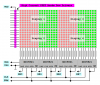
I have solved the brightness issue in the 16x16 LED matrix by going back and reading closely some earlier posts.
1. I am using ULN2803s with current limiting resistors (I have used 22 ohm and 100 ohm and their is no over or under brightning differences like I saw before) on the cathodes.
2. I have replaced the UDN2982s / (or previously used transistor/resistor circuits) on the 16 Anodes and removed the current limiting resistors (now on the ULN2803 outputs going to the 16 cathodes).
3. I am now using 2.4 Amp P channel FETs. They are surface mount (extremely tiny) components on the Anodes. The Source lines are tied to +5vdc. The gates are connected to the SX52 outputs and the Drains are connected to the 16 Anodes. I had to make a PCB (etched from Radio Shack kit) to hold the 16 P-FETs and run wires to the solderless breadboarded test setup with the components and 16x16 LED matrix.
At first I noticed that when scanning the columns (as I did before) that when more than 5 LEDs were on in any row they were dimmer than the rest. However, when I had the rows scanned (Anodes) WOW... ALL THE LEDs were on with the same brightness!!! This is because the P-FETS were drawing more current. It did not seem to matter (as it did before when scanning the collumns) of the current limiting resistor values (e.g. 100 ohm, 10 ohm). I had now set the first 8 columns with 22 ohm and the 2nd 8 columns with 100 ohm resistors but all the LEDs had the same great level of brightness. Not super blinding but a nice consistency accross the board of the 16x16 LED matrix.
It was amazing to me that I needed to replace the row drivers with the P-FETS AND I needed to scroll the rows (Anodes) and not the columns as done before. What a difference!
i still drawing less then an Amp so I can use the Parallax normal 7.5 vdc 1 A supply going into the SX52 Protoboard (regulated to 5vdc).
I hope to have some continuing great progress on my design this weekend - now that the brightness issue is solved completely. The only downside is that I if I want to maintain the constant brightness across all the LEDs then I can not scan the cathode columns (only the rows - Anodes).
I got the brightness issue solved!!!
I have solved the brightness issue in the 16x16 LED matrix by going back and reading closely some earlier posts.
1. I am using ULN2803s with current limiting resistors (I have used 22 ohm and 100 ohm and their is no over or under brightning differences like I saw before) on the cathodes.
2. I have replaced the UDN2982s / (or previously used transistor/resistor circuits) on the 16 Anodes and removed the current limiting resistors (now on the ULN2803 outputs going to the 16 cathodes).
3. I am now using 2.4 Amp P channel FETs. They are surface mount (extremely tiny) components on the Anodes. The Source lines are tied to +5vdc. The gates are connected to the SX52 outputs and the Drains are connected to the 16 Anodes. I had to make a PCB (etched from Radio Shack kit) to hold the 16 P-FETs and run wires to the solderless breadboarded test setup with the components and 16x16 LED matrix.
At first I noticed that when scanning the columns (as I did before) that when more than 5 LEDs were on in any row they were dimmer than the rest. However, when I had the rows scanned (Anodes) WOW... ALL THE LEDs were on with the same brightness!!! This is because the P-FETS were drawing more current. It did not seem to matter (as it did before when scanning the collumns) of the current limiting resistor values (e.g. 100 ohm, 10 ohm). I had now set the first 8 columns with 22 ohm and the 2nd 8 columns with 100 ohm resistors but all the LEDs had the same great level of brightness. Not super blinding but a nice consistency accross the board of the 16x16 LED matrix.
It was amazing to me that I needed to replace the row drivers with the P-FETS AND I needed to scroll the rows (Anodes) and not the columns as done before. What a difference!
i still drawing less then an Amp so I can use the Parallax normal 7.5 vdc 1 A supply going into the SX52 Protoboard (regulated to 5vdc).
I hope to have some continuing great progress on my design this weekend - now that the brightness issue is solved completely. The only downside is that I if I want to maintain the constant brightness across all the LEDs then I can not scan the cathode columns (only the rows - Anodes).