Continue to Site

Welcome to our site!

Electro Tech is an online community (with over 170,000 members) who enjoy talking about and building electronic circuits, projects and gadgets. To participate you need to register. Registration is free. Click here to register now.

  • Welcome to our site! Electro Tech is an online community (with over 170,000 members) who enjoy talking about and building electronic circuits, projects and gadgets. To participate you need to register. Registration is free. Click here to register now.

Driving LED Dot Matrix Bright?

Status
Not open for further replies.
arrow said:
Hi Nigel

I have just tried to source the ULN2981 with no success.

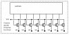
Can you please recommend a part number for the discrete transistors that will do the same job? (Source 140mA and driven by the 74HCT595).

I appreciate your help.
Regards
a.

Perhaps if you had your location entered in your profile we might know where you are?, then we could perhaps make informed suggestions?.
 
Hi Nigel

I am in South Africa, where a lot of the components are either not available, or there is a long lead time. That is why I am looking at discreet parts as you suggested.

Regards
a.
 
Arrow,

The ULN2803 is a 'sinking' driver... Don't you want a 'source' driver to drive the Common Anode columns?

The other part you were looking for is an Allegro UDN2981A 'source' driver, not a ULN2981A...

Here's an 'HC595/Transistor example (one of many many different ways to do it)... I forgot to include the current limiting resistors between the transistors and the CA connections...

Regards, Mike
 

Attachments

  • ca_column_driver_example.jpg
    ca_column_driver_example.jpg
    30.3 KB · Views: 1,235
Hi Mike

Thank you for your diagram. I shall try it.
Can you please recommend a part number (wiht sufficient current) for the transistor?

All the best
a.
 
regarding my previous question:

using the 2803 as a current sink for LEDs , not a source... do I need to worry about connecting the COM pin to anything? LEDs don't generate much by the way of inductive kickback right?

reply to arrow:

choose a PNP darlington, TIP105, TIP30, etc... or something smaller, like a BC series - how much current did you need to source again?
 
Hi JustDIY

Thank you for your reply.
I need to source 140mA- will the parts you recommend work (I need a through hole component)?
and What should Vcc be- will 5V be enough?

The circuit diagrams I have seen leave COM open on the 2803.

Regards
a.
 
arrow said:
I need to source 140mA- will the parts you recommend work (I need a through hole component)? and What should Vcc be- will 5V be enough?

140ma - no sweat!

get a hold of some 2N3906 transistors ... they are through hole and should be super cheap ... each can handle 200mA continous. Something like the 2N4403 can handle 600mA, but when you start getting into the higher currents, you really need a darlington, because the base current demands start getting pretty bad - hopefully someone with a better understanding can clarify this some - I just have a loose handle on the idea. of course, if money is no object (haha), you could use p-channel mosfets, which can source unbelievable amounts of current with next to nothing in terms of gate current (they rely more on gate voltage)

if you're looking for a place to buy the 3906 (or others), Futurlec ships all over the world, for a pretty low price (they tend to be a bit slow at times, not the best choice if you're faced with a deadline)

5V for VCC is fine for the HC or HCT series of the 595... I haven't worked with other series, so I couldn't say for sure (I think the LS series requires TTL voltages, 12v?)

keep in mind the transistor will be inverting your signal from the 595, so when you set an output in your register to 0, the transistor will come on ... setting the output to 1 will turn off the transistor.
 
Hi JustDIY

Thank you for the information.

I have sourced the parts you suggest.

I am really struggling with this dot matrix though. Since you have been so helpful, may I ask you a question on it?

What I find when I use the 74HCT595 is that when there is say a 100ms delay as I activate one column at a time on the dot matrix- things work fine. (I have my OE line on ground- pin 13 on the 595).
Now I remove the 100ms delay and I get terrible ghosting.
I then control pin 13 by setting it LOW during the shifting to outputs, and then HIGH after I am finishing- this switches off all outputs. The ghosting dissapears then, but I have a much smaller duty cycle and the LED's glow much dimmer.

Can you please tell me what I am doing wrong?

Thank you
a.
 
your problem sounds like a software timing issue and just a common attribute of human vision called persistance

the faster you scan your matrix, the less time the LEDs stay on, which means the less time your eye and brain have to integerate the light emitted. the other side effect is the leds which are actually "off" still look like they are on, because the eye and brain haven't realized the led has turned off.

there are two ways to combat the dimming of leds, first, push your LEDs with as much current as they can handle - since they'll only be on for a short fraction of a second, this will help squeeze every last drop of brightness from them. second, add a small delay, I found a good delay for my matrix by using some buttons with my microcontroller, each press would increase the scanning speed (decreasing the delay)... I adjusted it to a number that gives me the most brightness but still fast enough to not notice a flicker (from the updating)

to help with the apperance of more leds being on is also solvable in software... think of each 'update' you do to your array as a 'frame' - if you just flash each frame once on the array, your eye and brain might not have enough time to integerate the pattern clearly. try updating your array several times with the same data, before moving onto the next 'frame', each update gives your brain a little more information about the pattern it is seeing. depending on how big your array is and how complex the data being displayed is, you may only need to do each 'frame' twice, or you might need to do each ten times.

I hope this is some help to you - I'm new to LED matrices as well - I have some pcb layouts drawn up and plan to make some 8x8 display modules this upcoming weekend. I've written about what I'm up to on my blog, you can read about the 8x8 matrix here and continued here.

ttyl!
 
Hi Just DIY

After much effort I managed to change my 7x5display into scanning across the rows.
Now the display is much brighter BUT still not fully bright.

My previous problem was that my voltage regulator was only providing 100mA and was getting VERY hot when it was driven to 150mA. Now I use the power from the transofrmer direclty and that is rated to 500mA.

Instead of using NPNs I am back to using the ULN2003 to sink the current.
I measure the current sourced by the 595 and its only 12mA per pin.
I am wondering if there is any way to increase this.

Total sourcing of current from the transfomer is 161mA.

Can you help me to increase the current out of each pin of the 595 please?

Thank you and
Regards
a.
 
since you are seeing a current draw of 161mA from your supply, you are driving your LEDs as hard as is recommended already 7 leds in a column * 20mA each = 140 mA

the only way to improve brightness is to adjust your timing, scan faster or slower. it could be you've reached the limit as well. I've tried a number of different methods to drive my small array... but all yield the similar brightness but are still is dimmer than if I just connect all the anodes to v+ and all the cathodes to gnd (with resistors of cource)

the 12mA you are seeing is an average current as sampled by your multimeter ... you'll need to freeze the array in order to get an accurate current reading for a row or column.
 
Hi JustDIY

Thank you for your help.
I have changd the circuit to scan over the rows and it works much better.

I have also put in the 7805 Voltage regulator.

Its getting very hot now- I have about 275mA going through it and an AC component of approximately 75mA.
I was wondering if you could tell me if there is any way to heat sink it?
Is it normal that its running so hot? (I can smell it).

I am also going to post this question on a new thread.

I appreciate all your help.
Regards
a.
 
Status
Not open for further replies.

New Articles From Microcontroller Tips

Back
Top