Continue to Site

Welcome to our site!

Electro Tech is an online community (with over 170,000 members) who enjoy talking about and building electronic circuits, projects and gadgets. To participate you need to register. Registration is free. Click here to register now.

  • Welcome to our site! Electro Tech is an online community (with over 170,000 members) who enjoy talking about and building electronic circuits, projects and gadgets. To participate you need to register. Registration is free. Click here to register now.

Driving DIN power relay with SSR and uC

Status
Not open for further replies.

nickagian

Member
Hi!

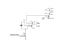
Attached is a draft schematic of a circuit that I have in mind. I want to drive a DIN power relay (for example the A9C21732 contactor (220VAC, 25A) from Schneider-Electric or some other similar part and I'll build a PCB with a uC to control it. On the PCB I'll put a solid state relay, the output of which will drive the power relay. My question is, what SSR should I choose to correctly drive the power relay? The maximum output current of the SSR is my main concern. Does the power relay have any specific coil drive current specification that I should have in mind? How much coil current is needed to be activated?
 

Attachments

  • relay.PNG
    relay.PNG
    13 KB · Views: 350
Do you have a link to the relay you plan to use? The data sheet on the chosen relay should provide the coil current and the coil inrush current. Your choice in SSR should be able to easily handle the coil current. If possible look for a SSR with zero crossover on / off.

Ron
 
Hi Ron, thanks for your reply.

The relay that I plan to use is the A9C21732 relay from schneider-electric.

A9C21732 relay

Is it the inrush and holding consumption (written at the second page) that I'm looking for? I am not very familiar with relays, that's the reason for my noob questions.

And regarding the zero crossover characteristic of the SSR, why is this so important? What does this practically mean?
 
Last edited:
Hi There

OK, you are currently looking at using a small SSR to work as a slave to a large contactor. Looking at your circuit you are using Q1 a mosfet to drive your slave relay. If the mosfet is driven from a uC the mosfet will need to be a logic level mosfet if we assume you only have 5 volts of gate drive from the uC. Thus a logic level mosfet.

The contactor coil current is next to nothing even with the inrush current. Actually (and I may be wrong) your coil current is well below 100 mA worst case. Just about all SSRs have leakage so you really need a very low current SSR. Not a big problem but all things considered have you given any thought to just driving a SSR directly from the uC? Even if the uC could not directly drive the SSR a simple transistor could be used to drive the SSR from the uC.

I use SSRs to drive 480 VAC heater elements drawing 60 Amps per leg in 3 phase circuits. The majority running well over 10 years. :)

<EDIT> Oh, as to zero crossover I wouldn't worry about it. The idea is the SSR will only switch as the sine crosses zero. <EDIT>

Ron
 
Last edited:
Hi again

well, to put my thoughts down:

1)If I understand correctly you say that the contactor will probably require around 100 mA of current (this is I guess calculated from the inrush power consumption mentioned in the datasheet). Do you have any specific SSR in mind that would suit my case? Would this be OK?

2)Why do you say that it would -probably- be better to drive the SSR with a pnp transistor and not a MOSFET? I'm not yet sure if the uC can drive the SSR, because I haven't chosen the SSR and I don't know if the maximum current for the uC's pins is enough.

3)In fact, I was considering the solution of using only one relay (an SSR) and directly driving my load, without the use of the contactor. My load is actually a 220VAC/25A water heater. Is this a good solution? What SSR would you recommend me for this purpose? I've never bought any SSR before and I don't know anything about the available manufacturers.

I am mostly concerned about the mechanical mounting and the safety of the SSR. That's the reason why I thought that using a contactor (which is designed for directly mounting on the distribution board, will give sufficient heat conduction and is completely protected from direct human contact) to drive the load would be the best idea. But of course, if I overcome this issue, using a sole SSR to directly drive the load would be a more compact solution.
 
Last edited:
The linked to SSR should work.

As to the mosfet, what I was getting at was that you mentioned driving the mosfet from a uC. That means as I see it that your gate voltage to the mosfet will be 5 volts. Therefore you would need a "logic level mosfet". Logic level mosfets are mosfets designed to work (fully turn on) with a low gate voltage like your uC output.

Ron
 
Thanks Ron for all your help. One last question... What happens if the current drawn by the load is below the minimum load current of the relay? For example check this relay. It says that its min load current is 25mA. If the load connected to the relay needs less current, the relay is not able to drive this load? Thanks again!

Nick
 
Last edited:
Thanks Ron for all your help. One last question... What happens if the current drawn by the load is below the minimum load current of the relay? For example check this relay. It says that its min load current is 25mA. If the load connected to the relay needs less current, the relay is not able to drive this load? Thanks again!

Nick

Hi Nick

Unfortunately the relay link took me to an international Farnell page but no product. :(

However, if the minimum load is not met there is a good possibility the SSR will not snap on. Thus when you look at an SCR data sheet they spec a min and max load. This is a much more detailed explenation:
Minimum load current is the least amount of current that the SSR will switch on and continue to carry with a nominal output voltage drop. Load currents less than this value may not be switched by the SSR. Typical minimum load currents are 50 to 100 mA rms.

One means of determining that there is a potential compatibility problem, aside from published specifications, is that the forward voltage drop across the relay will be in excess of the specification. Another means is that the load does not fully turn on or operate correctly. This is due to excess voltage drop in the SSR because it is not able to turn on fully.

A RC snubber network adds leakage current to the SSR. In cases where loads are very light, the snubber leakage current can become a significant percentage of the total load current. E.g.: a SSR with snubber leakage current of 10 mA would be 25 % of a 40 mA relay coil or solenoid. Generally, that is enough current to keep the load latched on. The best choice in such a case would be to employ a SSR with out a RC network, or at least an SSR with a small RC network. The alternative is to add a parallel bypass shunt resistor around the load to decrease the leakage current component going through the load.

Note there is a work around.

Before I forget the above quote was taken from here and opens as a MS Word document.

Ron
 
Hi Nick

Unfortunately the relay link took me to an international Farnell page but no product. :(

I'm sorry for that Ron... I was talking about **broken link removed** from CRYDOM (just an example).

So, this relay says that the minimum load current is 25mA. In such case, my A9C21732 contactor with 2.7VA holding power (aka ~12mA rms) would pose a serious problem.

However, if the minimum load is not met there is a good possibility the SSR will not snap on. Thus when you look at an SCR data sheet they spec a min and max load. This is a much more detailed explenation:


Note there is a work around.

Ron

With the work around you mean the use of the parallel bypass shunt resistor mentioned in the MS Word document you linked?

So, if I understand correctly, I should either use a parallel bypass shunt resistor or use a relay that will directly switch my load, and forget about the A9C21732 contactor.

xmmm.. I don't know what would be the best solution.
 
Yeah, that is about it in a nutshell. Generally as I initially suggested I would come off the micro controller and depending on how much current the uC can output I would either directly drive a SSR or if the uC lacked the current to drive an SSR (Typically about 10 mA min) I would have the uC drive a transistor to drive the SSR. Should those options not be practical then I would just shunt the contactor coil and work from that angle. Pretty much your call as to how you choose to go about it.

Now if the current through the contactor is high current then there is a need for good heat sinking, so that would need considered if a SSR replaced the contactor.

Ron
 
i would simply buy a 30+ amp ssr ( input signal is generally 3-32V) and drive it directly with your 5 volt signal, dont use contactor on heaters, they wont last long if you need precise temperature control (a lot of on/off cycle).
 
Status
Not open for further replies.

Latest threads

New Articles From Microcontroller Tips

Back
Top