ahmedragia21
Member
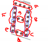
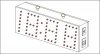
Hi, im trying to make a big digital clock , each segment is described as in the picture , the problem is i know how to drive 7-segment displays using BCD to 7-seg decoder , but in the display for example 00:00 has more than 7 segments as shown , what kind of decoder should i use ?
")