Continue to Site

Welcome to our site!

Electro Tech is an online community (with over 170,000 members) who enjoy talking about and building electronic circuits, projects and gadgets. To participate you need to register. Registration is free. Click here to register now.

  • Welcome to our site! Electro Tech is an online community (with over 170,000 members) who enjoy talking about and building electronic circuits, projects and gadgets. To participate you need to register. Registration is free. Click here to register now.

driving a transformer using a signal generator

Status
Not open for further replies.

julesison

New Member
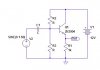
hi, sorry if this has been solved/posted etc before i suffer from ads which is a great excuse for a short attention span, in other words i haven't searched past posts, alias lazy bugger. i have a standard 600 ohm output signal generator and want to experiment with frequency, wave forms, amplitude etc on home made/wound ferrite transformers. if i feed my sig gen into a emitter follower (high imp in, low out) as per the cct attached, and "ground" my negative sig gen output to the negative rail of the cct should that be ok? r2 and r3 10k for near unity gain and r2 a bit higher for some usable gain? as i'm messing with 25khz + c1 could be 1uf? i'm obviously "green" on all this so any help greatly appreciated, and i apologise for any stupid questions in advance, thanks.
 

Attachments

  • Screen Shot 2015-11-29 at 3.17.55 pm.jpg
    Screen Shot 2015-11-29 at 3.17.55 pm.jpg
    23.3 KB · Views: 242
Hi julesison,
An emitter follower always has a voltage gain of slightly less than 1. The ratio of R2 an R3 do not effect the voltage gain. They only set the bias voltage on the base of the transistor so with equal values in your circuit the base will be about + 6 volts. (This is assuming an insignificant base current with respect to the current through these resistors.) This means that the emitter will be a about + 5.3 volts. You need a lower value resistor for R1 so that it can drive the output signal negative (With respect to is DC voltage level.) R1 needs to be about equal to the output impedance you require. This probably means that you will have to reduce the values of R2 and R3 so that the required base current does not affect the DC conditions significantly. (You will need to know the minimum hfe value for the transistor.) If you use the circuit as drawn to drive an inductor then you will be passing a DC current through the inductor which may cause two problems. 1 It may cause saturation in the inductor. 2 It will effect the DC conditions in the emitter follower and may cause distortion and it could burn out the transistor if it is trying to develop about 5.3 volts across a very low resistance. A capacitor between the emitter and the load will solve this problem. A 1 uf capacitor for C1 at 25 Khz would have a reactance of about 6.4 ohms so that should be OK. I think using an audio amplifier IC would be a better solution than an emitter follower.

Les.
 
I think using an audio amplifier IC would be a better solution than an emitter follower.
I agree, much better in many ways.
JimB
 
firstly, thank you for your prompt response, secondly i'm not sure i explained myself that well. as the frequencies could well be higher than 25khz, an audio amp might have a problem? also as the transformers under test will vary i cannot guess/guarantee the input impedance will suit the 4-16 ohms an audio amp is happy with. is there not a "universal" impedance matching, "buffer" type device? i attach a rough pic of what seems to me the perfect "cct". it would be basically a cct that allowed a signal generator to "modulate" the dc from a bench top power supply. for the sake of convenience it wouldn't have to swing + and -, it could be a square or sine all above zero. the power supply can be the current limiter through it's current output adjustment. i just need something that shows a high impedance to the sig gen output and that doesn't care about the output as it's current limited via the power supply anyway. surely this is the easiest way to be able to test "any" winding/transformer? sorry again if my simplistic approach is off but logically it seems sound?
 

Attachments

  • cct_diagram_1.jpg
    cct_diagram_1.jpg
    104.7 KB · Views: 203
Most audio amplifiers work perfectly if their load is 4 ohms, 20 ohms, 2k ohms or infinity. We never match impedances because most audio amplifiers have an output impedance of 0.04 ohms or less so that they can damp the resonances of an 8 ohm speaker.

Audio goes as high as 20kHz but most audio amplifiers go to 100kHz or more to make sure that the response at 20kHz is level with low distortion.
A cheap little LM386 IC audio amplifier produces an output of 1/2W into 8 ohms with a 9V supply voltage. Its output level is almost flat up to 100kHz.

Usually an output coupling capacitor is used if the supply is not plus and minus voltages so that the output DC voltage is blocked but the AC modulation is passed. You do not want DC in a speaker nor in a transformer.
 
hi ag, thanks for the info, didn't appreciate the "misrepresented specs", although truth be told they only have to cover the audio pertinent spectrum detail i guess. so the 4-16 ohms stated output impedance is a damping thing for the speaker rather than an amp requirement? so if i can be lazy for a moment, if i use a amplifier module like the one attached i should not have a problem with lower than 4 ohms impedance, (if i end up with that) especially if i can limit the current via the power supply? thanks again
 

Attachments

  • Screen Shot 2015-11-30 at 12.54.24 pm.jpg
    Screen Shot 2015-11-30 at 12.54.24 pm.jpg
    42.7 KB · Views: 149
  • Screen Shot 2015-11-30 at 12.53.46 pm.jpg
    Screen Shot 2015-11-30 at 12.53.46 pm.jpg
    52.2 KB · Views: 174
Most amplifiers can drive a speaker that is 4 ohms to 16 ohms.
The Kemo amplifier has horrible spec's maybe because of a translation problem:
1) Its output impedance range is not 4 ohms, instead its load can be 4-16 ohms.
2) Its power output must list the actual supply voltage used for the measurement, the frequency and the distortion.
3) The frequency response must be a range from one frequency (20Hz?) to another frequency (20kHz?) with the amount of deviation (plus or minus 1dB?). The Kemo amplifier does not mention anywhere near 25kHz.
4) The voltage source is listed as 6V at 800mA which is 4.8W. Much of that power is heat so the speaker gets maybe 2.8W but 12W is wrongly listed. How much power does your transformer need?
 
hi ag, i picked that amp as i had a jaycar catalogue on the table.
1) most audio amps list load impedance as 4-16 ohms, especially the cheaper, modular ones and you said in a previous post that they will drive less and the impedance requirement is for damping?
2) we're talking a budget modular package here, again chosen by what was at hand but i would assume the "standard" specs
3) on my page it says 40 - 20khz
4) the front of the casing says supply voltage 6-16 vdc

- if you could suggest a better modular amp i would be grateful
- there will be a range of transformers and while the voltage and amperage are not important per se (it is the winding types and placements that are being tested, so as long as they are all done using the same voltage and current it is ok) i would envisage 3-12 volts and 100-300mA
 
Hi julesison,
You need to give a full specification of your requirements.

Minimum frequency.
Maximum frequency
maximum RMS voltage output
minimum load impedance of transformer under test. (So that the maximum output current can be calculated.)

Although an audio amplifier rated for use with a 4 ohm speaker can drive a load of less than 4 ohms it can only do so at reduced power so as not to exceed the current rating of the output devices. So as an example a 10 watt amplifier can give a maximum of 10 watts into a 4 ohm load. This will be 6.3 volts RMS and a current of 1.59 amps. so if you had a 1 ohm load you can still only have a maximum current 1.59 amps. this would mean the maximum voltage output could only be allowed to be 1.59 volts (i.e. 2.53 watts.) At higher load impedances than 4 ohms the output voltage is still limited to 6.3 volts RMS so you would again be limited less than 10 watts. It is possible that there are some high power video amplifiers available to meet your requirements.

Les.
 
3V RMS at 100mA RMS is a resistance of 30 ohms at 300mW that any audio amplifier can drive if the frequency is within its bandpass.
12V RMS at 300mA RMS is a resistance of 40 ohms at 3.6W which is too high for most little amplifiers and the amplifier (a TDA2030A can do it) will need a power supply of maybe 40V to produce 12V RMS.

The Kemo is the only "modular" amplifier that I have ever seen. Usually we use an amplifier IC and build it into the circuit shown on its detailed datasheet. The Kemo does not show its circuit and it does not have a detailed datasheet. For example you said its frequency response is from 40Hz to 20kHz but the detail of how much it deviates is missing. It might produce an output level of -60dB at 20kHz which is almost nothing but it is responding.
 
Hi julesison,
This seems a very expensive solution to the problem. I do not understand the significance of the question marks after your first two statements. The 6 ohm resistor should provide enough protection as the amplifier is rated for a 4 ohm load.

Les.
 
my problem is time. i have 3 weeks to finish my testing so while others may have the time and wherewithall to build the necessary for 1/10th the price, i do not, so thanks for confirming the current limiting resistance and now i can get on with it.
 
The Digitech amplifier description and specs from Jaycar sounds fishy. Its input power is from a little adapter instead of built into it and is rated at only 18V at 2.2A= 39.6W. The amplifier circuit is probably class-AB so almost half the input power produces heat then each channel can produce only about 12W, not 25W. It has ONLY microphone inputs so many signals will need to be attenuated down to mic levels.

An amplifier designed to drive a speaker must not have any DC on its output so it does not need an additional capacitor to block DC.
By the way, if its spec for frequency response is truthful then at 65kHz its output is -3dB which is half the power or 0.707 times the voltage of a signal at 1kHz.
 
Status
Not open for further replies.

Latest threads

New Articles From Microcontroller Tips

Back
Top