SGiard
Member
Big hello to everybody on this wonderful forum and thanks to the guy(s) (and gals?) running it.
Recently I put my hands on an old 9 inch B&W TV. I have always dabbled in electronics and have always been fascinated with the CRT which frankly is a technology that still baffles me. Unfortunately, while
making tests I totally busted the PCB that was driving that tube, but I just can't throw it away. (I guess a lot of people here know that feeling). So now I would like to try and drive it myself just as a
learning experience. I have a couple of old flyback transformers that I know how to drive so the HV part is not the problem. I also do not care about the horizontal / vertical deflection stuff.
My goal is simply to be able to produce a nice white (bluish) dot in the center of the tube.
The problem is I have only the vaguest idea of what voltages I should apply to the pins at base of the neck of the CRT.
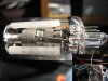
I have included a picture of the tube with an insert showing the connector for it.
Here is the pinout of the tube (which is a Matsushita 230ADB4 by the way, I didn't find any specs on the Net and it is not for lack of trying. Does anybody have a spec sheet somewhere?):
Pin 1: Green wire
I know this is the video signal input. I figured that out before busting the board.
Pin 2: Not used, (internally connected to pin 6)
Pin 3: Blue wire
Pin 4: Red Wire
There is very low resistance between those two pins so I think that would be the heater connection but I don't know the range of voltage / current (AC ? / DC ?) I should apply there.
Pin 5: Yellow wire
Pin 6: Orange wire
Pin 7: White wire
These pins are connected to the "electron gun" of the tube.
Pin 5 is connected to the part nearest the pins. (The cathode? Should I put it to ground?)
Pin 6 is connected to the smaller middle part.
Pin 7 is connected to most forward part
Can anybody help me complete the picture?
Thanks in advance...
Recently I put my hands on an old 9 inch B&W TV. I have always dabbled in electronics and have always been fascinated with the CRT which frankly is a technology that still baffles me. Unfortunately, while
making tests I totally busted the PCB that was driving that tube, but I just can't throw it away. (I guess a lot of people here know that feeling). So now I would like to try and drive it myself just as a
learning experience. I have a couple of old flyback transformers that I know how to drive so the HV part is not the problem. I also do not care about the horizontal / vertical deflection stuff.
My goal is simply to be able to produce a nice white (bluish) dot in the center of the tube.
The problem is I have only the vaguest idea of what voltages I should apply to the pins at base of the neck of the CRT.
I have included a picture of the tube with an insert showing the connector for it.
Here is the pinout of the tube (which is a Matsushita 230ADB4 by the way, I didn't find any specs on the Net and it is not for lack of trying. Does anybody have a spec sheet somewhere?):
Pin 1: Green wire
I know this is the video signal input. I figured that out before busting the board.
Pin 2: Not used, (internally connected to pin 6)
Pin 3: Blue wire
Pin 4: Red Wire
There is very low resistance between those two pins so I think that would be the heater connection but I don't know the range of voltage / current (AC ? / DC ?) I should apply there.
Pin 5: Yellow wire
Pin 6: Orange wire
Pin 7: White wire
These pins are connected to the "electron gun" of the tube.
Pin 5 is connected to the part nearest the pins. (The cathode? Should I put it to ground?)
Pin 6 is connected to the smaller middle part.
Pin 7 is connected to most forward part
Can anybody help me complete the picture?
Thanks in advance...