Continue to Site

Welcome to our site!

Electro Tech is an online community (with over 170,000 members) who enjoy talking about and building electronic circuits, projects and gadgets. To participate you need to register. Registration is free. Click here to register now.

  • Welcome to our site! Electro Tech is an online community (with over 170,000 members) who enjoy talking about and building electronic circuits, projects and gadgets. To participate you need to register. Registration is free. Click here to register now.

Driving 4x7-Segment Display with a PIC

Status
Not open for further replies.

Tom81

Member
Hi Guys,

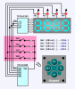
I'm designing a circuit to drive a 4x7 segment display using a PIC. I've done this in the past without any drama. I would just use four pins to control each of the four digits (one each). I'd switch one digit on, wait a bit, turn it off, then switch the second digit on etc.
Although I've found with this particular project, I'm going to be short some pins.

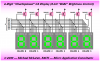
I was hoping that I could get away with using just one pin from the PIC and pulse it (square wave) through some interfacing electronics which would have four output pins that toggle on and off in a sequence, one at a time. (IE 1, 2, 3, 4, 1, 2, 3, 4 etc)

Does anyone of some electronics or an IC that would do this?

Additionally (just to make things more difficult), I'm a little tight for board space. Smaller the better.

Any help would be great... Cheers

-Tom
 
Have a look at the serial to parallel 74HC595 or equivalents. U can save many pins with that chip.
 
Or even better a 4511 BCD-7 segment driver chip, that even has high current capacity to feed the display - it's often used commercially to save pins when multiplexing 7 segment displays.
 
Have a look at the MM5450.
It is an LED driver IC, it will drive four seven segments displays and you only need two pins, data and clock on the PIC to drive it.

JimB
 
Alternatively, what about the SAA1064 4 digit LED driver with I2C bus and just bit bang the data over a couple of pins?
 
As the guys have mentioned, once you've decided to add a chip, there's lots of design choices. Here's yet another example to throw into the mix;

Good luck on your project...

macmux-4-digit-16f88-demo-png.54008
 

Attachments

  • MacMux 4-Digit 16F88 Demo.PNG
    MacMux 4-Digit 16F88 Demo.PNG
    17.9 KB · Views: 2,433
  • LED_4-Digit_595.c.txt
    9.3 KB · Views: 407
Last edited:
Another option to consider is to use an 8-bit shift register (like the 74HC595) to connect to the 8 segments, and drive the common cathode/anode pin using a transistor. This will require 6 pins, 3 for the shift register and 4 for the digits.
Or you can do it with 2 pins and some transistors.

 
Last edited:
Program a second pic to just handle the display and communicate with 1 line. A 16F88 would handle it very well.

Mike.
 
If everyone posts an example of their suggestion we could make a sticky. Everyone needs this at some point.
 
Tom,

If board space is tight and you don't have room for an extra chip, you might consider Charlieplexing the display. The "up side" is you only need eight (8) pins and you should get the same brightness and performance you're getting now (with direct segment drive). The "down side" is the funky display wiring.

Regards, Mike
 

Attachments

  • Charlie #1.png
    Charlie #1.png
    39.9 KB · Views: 903
Last edited:
Hi all,

This is really great feedback - thanks for everyone's input - lots of choices!

The last project I used a 4x7seg display and switched each digit on/off with NPN transistors and drove each segment directly (via resistors) from the PIC. On a side note, I used PIC16F88. See image below.
S5001054_B.JPG
This is an older one I did some time ago. As you can see, the board's getting pretty cramped. Although I was fairly happy with the current usage (overall about 70mA including running the sensor on the board). And it was quite an effective little unit.

I have previously used a 4511 BCD Driver with good results too. The downside to this is you're restricted to 0-9, A-F.

I'll go into a bit more detail with the current application...

It's a small display. Actually, the board size limitations are a mere 20x45mm! This is just about enough space to fit the 3x7seg display, plus a PIC16F88 (SOIC package).

If I can use both sides of the board, I should be able to fit the remaining components (reg, caps, transistors, resistors etc).

Adding another PIC would be great, although I'm not sure I'd have enough board space to accommodate both PICs. I like the idea of the 74HC595 though. Looks very compact.

Another question - I've seen some projects where the LED/segments have been driven directly from the PIC (with no resistors) and reduced using PWM. If the overall current consumption is within the PIC's limitations, is this ok to do? Or should I just steer clear from this method altogether?

Again, thanks for everyone's contributions. Much appreciated.

Cheers -Tom
 
Hi all,
It's a small display. Actually, the board size limitations are a mere 20x45mm! This is just about enough space to fit the 3x7seg display, plus a PIC16F88 (SOIC package).
Cheers -Tom

Sorry, I should have mentioned - I've now chosen a 3x7seg display to save on board space (instead of 4x7seg as originally posted).
 
You must use resistors so the outputs go fully HIGH.
Are you using dp?
How many micro lines do you have?
 
Looks like you're making a pressure gauge of some sort. That's a motorola sensor there.
 
Hi Tom81,

Just take a look at this link http://www.josepino.com/?anp-1224hr-led-clock1 I made this clock 18 months ago it has NO resistors unless you count the one for the AM/PM led if used, and has been running faultlessly ever since.

Jose's use of charlieplexing is the key to size and component numbers and as said earlier in this thread the only downside is the strange segment wiring, but it definately works well and saves space and components.

My build is just slightly bigger than the 4 LED displays I used but that was with TTH PIC and not SMT that you are using, just imagine how small yours could be!

Al
 
The Pino Clock circuit mentioned above has a number of faults:
**broken link removed**

The problem with NOT USING resistors is this:

The output is not going fully HIGH. It is only going to between 1.7v and 2.3v. This means the FET inside the micro is dropping 2.7v to 3.3v @ 25mA and this is a much higher wattage than the manufacturer of the chip has allowed-for. The chip has been designed for 25mA from each output but the output must be allowed to rise to nearly 5v.
With Pino's faulty design the chip can be dissipating between 460mW and 660mW.
It may run faultlessly but it is a bad design, and even-more damaging to present it on the web as a way to design microcontroller projects.
Two further points to note:
The PIC16F84A has now been replaced by the cheaper PIC16F628A.
At some point in the running of the program, one output going to the switches will be HIGH and the other will be LOW. The switch will short-circuit these two outputs. This should not be done.

It's like the Indian designs in "Electronics For You" magazine, I mentioned in another posting. All the circuits in the magazine have flaws in their design.
 
Last edited:
Status
Not open for further replies.

Latest threads

New Articles From Microcontroller Tips

Back
Top