Continue to Site

Welcome to our site!

Electro Tech is an online community (with over 170,000 members) who enjoy talking about and building electronic circuits, projects and gadgets. To participate you need to register. Registration is free. Click here to register now.

  • Welcome to our site! Electro Tech is an online community (with over 170,000 members) who enjoy talking about and building electronic circuits, projects and gadgets. To participate you need to register. Registration is free. Click here to register now.

Drive KS0108 LCD in assembler

Status
Not open for further replies.

serenavv

New Member
Hello, i want to drive a 128x64 lcd display in assembler (i have wg12864 lcd)
I'm not able to use correctly enable..
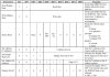
i found documents like the attached one, but i haven't exaustive information about enable...

for example... seeing the attachment i understand that...

1) i have to turn on the lcd (clear RS, RW, DB7, DB6 and set DB5, DB4, DB3, DB2, DB1, DB0)

2) set Y (clear RS, RW, DB7, set DB6 and use DB5, DB4, DB3, DB2, DB1, DB0 to indicate Y)

3) set display start line (clear RS, RW, set DB7, DB6 and use DB5, DB4, DB3, DB2, DB1, DB0 to indicate the start line)

4) set X page (clear RS, RW, DB6, set DB7, DB5, DB4, DB3 and use DB2, DB1, DB0 to indicate X)

5) write data in ram (set RS, clear RW and use DB7, DB6 ... DB0 for data)

Is it correct?
I have to turn on the lcd as first operation or after the write ram process?

I have also to select left o right zone with CS1 and CS2, it's sufficient before writing data in ram?

and what about enable signal???

i'm trying with a 16F886 but i'm not able to control the display.

Thank you!
 

Attachments

  • KS0108..JPG
    KS0108..JPG
    106.2 KB · Views: 836
Here is the sequence I use to init my GLCD in asm.
Code:
InitLCD_1	bsf	b_LCD_CS1
		bsf	b_LCD_CS2
		movlw	0x3f
		call	WriteCMD
		movlw	0xc0
		call	WriteCMD
		movlw	0x40
		call	WriteCMD
		movlw	0xb8
		call	WriteCMD

Mike.
 
It's a little tricky as this is part of a huge project but here are WriteCmd and WriteData.
Code:
WriteCMD	movwf	LCDTemp
		call	WaitNotBusy
		movfw	LCDTemp
		movwf	PORTB
		bcf	b_LCD_RW
		bcf	b_LCD_RS
		bsf	b_LCD_E
		bcf	b_LCD_E
		return

WriteData	movwf	LCDTemp
		call	WaitNotBusy
		movfw	LCDTemp
		btfsc	b_Inverted
		xorlw	0xff
		movwf	PORTB
		bcf	b_LCD_RW
		bsf	b_LCD_RS	;rs=1 rw=0
		bsf	b_LCD_E
		bcf	b_LCD_E
		return

And, preempting your next question, here is WaitNotBusy.
Code:
WaitNotBusy	bsf	STATUS,RP0
		movlw	0xff
		movwf	TRISB
		bcf	STATUS,RP0
		bsf	b_LCD_RW
		bcf	b_LCD_RS  
		btfss	b_LCD_CS1
		goto	Skip_CS1
		bcf	b_CS2
		btfsc	b_LCD_CS2
		bsf	b_CS2
		bcf	b_LCD_CS2
WNB1_Loop	bsf	b_LCD_E
		btfsc	PORTB,7
		goto	WNB1_Loop
		bcf	b_LCD_E
		btfsc	b_CS2
		bsf	b_LCD_CS2
Skip_CS1	btfss	b_LCD_CS2
		goto	Skip_CS2
		bcf	b_CS1
		btfsc	b_LCD_CS1
		bsf	b_CS1
		bcf	b_LCD_CS1
WNB2_Loop	bsf	b_LCD_E
		btfsc	PORTB,7
		goto	WNB2_Loop
		bcf	b_LCD_E
		btfsc	b_CS1
		bsf	b_LCD_CS1
Skip_CS2
SetOutput	bsf	STATUS,RP0
		clrf	TRISB
		bcf	STATUS,RP0
		return

All the variable that start with b_ are bit variables and b_LCD_CS1/2 are the port pins that the CS lines are connected to. It's a little tricky as I write to both displays at the same time when doing things like init or cls, hence the complexity of WaitNotBusy.

Mike.
 
I realize this is an old thread, but it is the simplest and easiest to understand initialization for the KS0108 in assembly I have found in the past week.

1) What is the difference between, for example, b_LCD_CS1 and b_CS1?
2) When a control bit is set for the LCD controller but a subsequent branch causes a return, is it necessary to repeat setting the bit? Or, is that just done to introduce a delay? If the return is due to "busy" does that change the answer?

Example:
Code:
wnb1_loop     bsf     b_LCD_E
              btfsc  PortB,7
              goto   wnb1_loop
              bcf     b_LCD_E

Would this work also, or does E need to be reset because of the busy?

Code:
wnb1_loop     bsf     b_LCD_E
             btfsc   PortB,7
             goto    $-1
             bcf      b_LCD_E

Thanks, John
 
Last edited:
1. There are two chip select lines and the variables b_CS1/2 are ram copies of b_LCD_CS1/2 so the CS lines can be put back to their original state at the end of WaitNotBusy. For doing things like initialise and clear screen both CS can be enabled together. Variables starting b_ are bit variables.
2. Either will work but I hate the goto $-1 thing. I'd rather see,
Code:
             bsf     b_LCD_E
wnb1_loop    btfsc   PortB,7
             goto    $-1
             bcf      b_LCD_E

The reason I don't like goto $-1 is because it is chip specific and won't work on an 18 series chip.

Edit, if you want ClearScreen, PlotPixel etc just let me know.
Edit2, here are some variable definitions that may help.
Code:
		cblock	0x20
Flags
Flags2
		endc

#define		b_CS1		Flags,0
#define		b_CS2		Flags,1
#define		b_100th		Flags,2
#define		b_Second	Flags,3
#define		b_Sign		Flags,4
#define		b_General	Flags,5
#define		b_Critical	Flags,6
#define 	b_NoEEPROM	Flags,7


;**********************************************************************
; Port Usage

;A0	
;A1	
;A2	CS1
;A3	CS2
;A4	
;A5	
;A6	
;A7	

;B0	d0
;B1	d1
;B2	d2
;B3	d3
;B4	d4
;B5	d5
;B6	d6 & Debug Clock
;B7	d7 & Debug Data

;C0	RW
;C1	Backlight PWM - CCP2
;C2	E
;C3	I²C
;C4	I²C
;C5	RS
;C6	TX
;C7	RX


#define		b_LCD_CS1	PORTA,2
#define		b_LCD_CS2	PORTA,3
#define		b_LCD_RS	PORTC,5
#define		b_LCD_RW	PORTC,0
#define		b_LCD_E		PORTC,2

Mike.
 
Last edited:
Just a pet peeve of mine...

The language is called ASSEMBLY, NOT "assembler". The "assembler" is the program that uses the assembly source code to generate the object file which holds the machine code that gets loaded onto the PIC.
 
@Pommie,

That clears it up perfectly. I assumed b_LCD_xxx were bits in a port based on the "LCD" part of the name but wasn't sure about the b_xxx.

I get your point on the $-1, but I think your illustration to avoid it may have a typo. It is clear what you meant, though.

Yes, I would like copies of those routines. Thank you for offering. Do you want to post here or send to my e-mail? After being immersed for a week, I am getting a better feel for what is being done. Heck, I found two MS theses on the Internet (U. Cincinnati and Cornell) where the final product was not much more than getting a character map to appear.

One thing I noticed is that at the hobbyist level, or even in the aforementioned theses, not a lot of attention appears to be paid to the power-up and power-down sequences shown in the datasheet. The NHD display I have does not have its own Vee generator. While the displays are probably tolerant to just having the power brought up with a switch, I contacted NHD technical service and was convinced to bring Vdd and Vee up and down in sequence. I will be doing that with the PIC and will probably generate Vee using a PWM output. I ordered some 28- and 40-pin versions that should be delivered this morning. Just FYI, I am getting the 16F887 that is popular as a fall back, the 16F1518/1519 with more than twice the memory at less cost (no EEPROM), and the 16F1938/1939. Therefore, I am no longer as pin-challenged as I was with my 20-pin 16F690.

Regards, John
 
Sorry for not getting back sooner, I've been at a wedding all weekend.

Anyway, here are some routines you may find useful,
Code:
Plot		call	SetLCDAddress
		clrf	Mask
		movfw	YPos
		andlw	0x07
		movwf	Count
		bsf	STATUS,C
GetBit		rlf	Mask,F
		decf	Count,F
		btfss	Count,7
		goto	GetBit
		call	ReadData	;dummy read
		call	ReadData
		iorwf	Mask,F
		movfw	XPos
		andlw	0x3f
		iorlw	0x40
		call	WriteCMD
		movfw	Mask
		call	WriteData
		return

SetLCDAddress	bcf	b_LCD_CS1
		bcf	b_LCD_CS2
		btfss	XPos,6
		bsf	b_LCD_CS1
		btfsc	XPos,6
		bsf	b_LCD_CS2
		movfw	XPos
		andlw	0x3f
		iorlw	0x40
		call	WriteCMD
		movfw	YPos
		movwf	Row
		rrf	Row,F
		rrf	Row,F
		rrf	Row,F
		movfw	Row
		andlw	0x7
		iorlw	0xb8
		goto	WriteCMD

Point		call	SetLCDAddress
		clrf	Mask
		movfw	YPos
		andlw	0x07
		movwf	Count
		bsf	STATUS,C
PntGetBit	rlf	Mask,F
		decf	Count,F
		btfss	Count,7
		goto	PntGetBit
		call	ReadDummy	;dummy read
		call	ReadData
		andwf	Mask,W
		return

UnPlot		call	SetLCDAddress
		movlw	0xff
		movwf	Mask
		movfw	YPos
		andlw	0x07
		movwf	Count
		bcf	STATUS,C
UnGetBit	rlf	Mask,F
		decf	Count,F
		btfss	Count,7
		goto	UnGetBit
		call	ReadDummy	;dummy read
		call	ReadData
		andwf	Mask,F
		movfw	XPos
		andlw	0x3f
		iorlw	0x40
		call	WriteCMD
		movfw	Mask
		call	WriteData
		return


Cls		bsf	b_LCD_CS1
		bsf	b_LCD_CS2
		movlw	0x08
		movwf	ForI
ClsLoopI	movlw	0x40
		movwf	ForJ
		call	WriteCMD
		decf	ForI,W
		iorlw	0xb8
		call	WriteCMD
ClsLoopK	movlw	0x00
		call	WriteData
		decfsz	ForJ,F
		goto	ClsLoopK
		decfsz	ForI,F
		goto	ClsLoopI
		clrf	XPos
		clrf	YPos
		return

Sorry about the complete lack of comments but it should, hopefully, be easy enough to understand. BTW, I think I did everything inverted so that it was blue on white.

Have fun.

Mike.
 
Thanks, Pommie.

That will keep me busy for a few days.

I created a flowchart for the initialization you posted above, which I am sure you don't need, but it might help other beginners like myself. There may be a few errors in it, but overall, it shows the clear symmetry of your process. I particularly like your use of meaningful labels. Comments weren't really needed.

One scheme I found on the Internet had dozens of macros, even one for "set E low" (just one step). I don't want to do that. But, considering that "Enable" is two instructions, do you see any advantage in adding a macro for Enable? I realize that in your program, the set and clear instructions are sometimes not used immediately one after the other. The question boils down to how common is it to use the two instructions one immediately after the other in programs that actually generate usable graphics?

John

Edit: I had to leave some arrows out that connect the processes at the start, because I am using the free version of the program and reached my "item" limit. I hope the flow is obvious.

View attachment 61235
 
Last edited:
Status
Not open for further replies.

Latest threads

New Articles From Microcontroller Tips

Back
Top