Continue to Site

Welcome to our site!

Electro Tech is an online community (with over 170,000 members) who enjoy talking about and building electronic circuits, projects and gadgets. To participate you need to register. Registration is free. Click here to register now.

  • Welcome to our site! Electro Tech is an online community (with over 170,000 members) who enjoy talking about and building electronic circuits, projects and gadgets. To participate you need to register. Registration is free. Click here to register now.

Drift/Noise problems for an Instrumentation Amplifier

Status
Not open for further replies.

Fish

New Member
Hello,

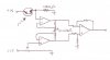
I'm trying to building a three-amp instrumentation amplifier similar to the one found at the link below.

http://www.ecircuitcenter.com/Circuits/instamp1/instamp1.htm

I am analyzing a small, ~10mV signal of varying frequency riding on top of a large DC offset, so I would like to use the negative input of the in-amp to null the DC component, and then amplify the ~10mV signal to about 5-10 V.

My problem is that the circuit works, but it's horribly, horribly noisy and seems to drift randomly after only a few minutes of operation (and this thing needs to remain stable on the scale of hours...). Both of these are serious defects since I'm working with a very small signal. RC low-pass filtering seems to help with some of the noise, but I can't set the cutoff frequency too low without distorting the signal. I haven't a clue on how to fix the drift problem.

Components in my circuit: the three op-amps are LF356, and I'm using carbon resistors with 5% tolerance, exact values matched using an digital multimeter. A 10-kOhm potentiometer is used to adjust the voltage offset into the negative input.

I'm a pretty much a complete newbie at electronics (practical, hands-on stuff, anyway), so if anyone has any suggestions on how to improve my work, any components recommended, and so forth, I would appreciate it.
 
The 3 stage fully diff setups are a huge problem in all the areas you specify.
1. The noise of all the amps and resistors is cumulative. You can select lower noise amps, or you can try to filter out the frequencies which are not what you're looking for.
2. The offset error and offset drift is cumulative. As you noticed, you can't predict the drift very effectively. Since you're looking for an AC signal, you might just filter the DC out through a capacitor. This works as long as the offset error doesn't cause the output to hit the limits of what the amp can put out. You can also look for lower offset op amps, or ones with lower offset drift so you can compensate for it with one adjustment.

I don't like these circuits at all myself. You can just buy a packaged "instrumentation amplifier" IC with a fixed gain (10x, 100x, whatever) and it does a much nicer job than discretes.

So do you really have a differential signal you need to measure? One other solution if the common mode voltage is going to be small, just use a differential op amp with 2 resistors. The prob is it does not have an extremely high input impedance, and the amplified output is added to the initial common mode voltage.
 
Well, it's not quite an AC signal... Without delving into the gruesome details of the experiment I'm doing, I guess I should have been a little more clear: the signal is of varying _low_ frequencies, and is actually DC at times, so I can't filter out DC components entirely.

And the offset is big: about 7 volts. I'm actually detecting variations in the output from a phototransistor operating between +15 V and ground. The device operates most linearly around 7 volts, so that's where I want my output to be nulled at.

But thank you for your suggestions. I was hoping to be able to work with what only things I have on hand, but I'll give the IC in-amps a thought now.
 
Fish said:
Well, it's not quite an AC signal... Without delving into the gruesome details of the experiment I'm doing, I guess I should have been a little more clear: the signal is of varying _low_ frequencies, and is actually DC at times, so I can't filter out DC components entirely.

And the offset is big: about 7 volts. I'm actually detecting variations in the output from a phototransistor operating between +15 V and ground. The device operates most linearly around 7 volts, so that's where I want my output to be nulled at.

But thank you for your suggestions. I was hoping to be able to work with what only things I have on hand, but I'll give the IC in-amps a thought now.

I think your biggest problem is your external resistor matching. Carbons are very bad for drift / matching and noise (you couldn't have picked a worse type to use :)
The iNAMP common mode rejection ability is a strong function of the very poor matching you have and so it is lousy and so will your output.

This is why someone mentioned the integrated version, these are much better because the external resistors are internal to the package and trimmed for accuracy and tracking (ratio's are low drift)

even if your signal is low freq, the CMRR is probably terrible at 60Hz and you might be getting a big component from that pickup in your output.

If you must build your own inamp, using precision metal-film resistor networks is a must in my opinion, you're guaranteed lousy performance otherwise. But with all time & money, you should consider buying the integrated version. Check www.linear.com, www.ti.com, www.analog.com
for many available part numbers.
 
Even if you use a great instrumentation amp and/or low tempco resistors,, the phototransistor will drift with temperature, the pot will drift, and the voltage you are biasing the pot with will drift unless you are using a precision reference. How do you plan to keep the phototransistor biased at 7 volts? What are you trying to detect? Are you sure there is no possibility of AC coupling, maybe even at very low frequency (sub 1 Hz)?
 
The phototransistor is used to detect very small motions of an object, whose neutral position leaves the phototransistor biassed at 7 volts. Unforunately, I can't divulge too many details about my experiment, for personal reasons (but I'm not engaged in anything illegal, in case anyone was thinking that).

I've tested the stability of my +/- 15 power source, which I am using for pretty much everything, and it seems very stable. I tracked it's output for 3 hours, and it remained at (15.000 +/- 0.001)V throughout.

But ack, this is getting more complicated than I thought. Phototransistor drift I'll have to think more about. But assuming the phototransistor had no or neglibile drift (ie. zero error), I would like to have the amplification/nulling circuit to be stable for at least 2-3 hours. Is this is possible (without having to pay an arm and a leg and possibly an eyeball)?

Forgive me if this is silly question, but what do you mean by "AC coupling", and how would I detect it?

Thanks everyone for your help so far.
 
You mentioned you wanted to amplify ~10mV to 10V and that is a gain of 1000.

I offer the idea of a chopper opamp ICL7650S which does not drift and maybe you would be able to use just it to obtain the required gain. However, this opamp has low value of supply voltage of +/- 8V max so is a little bit hard to use without an buffer.

So ideally you will scale down the input to about 50% and feed it through the 7650S opamp follows by another unity gain buffer which you can build using another opamp like 741. You need to keep the 741 inside the feedback loop to maintain the zero drift requirement. Search for the data sheet and take a look.
 
Big question is, why is the circuit wired so that the phototransistor signal isn't tied to ground?

Also are you sure you need a supply voltage that large? It rules out some good solutions. The best solution may be to just use a differential ADC, if this is a microcontroller system, but the signal must be 0-5v.

Outside of an ADC, you basically gotta have an instrumentation amp. That 3 amp diff circuit will never have an offset error anywhere near what you need. Plus it's just plain huge to wire.

Instrumentation amps are just a few $ usually.
 
Oh yeah, you can also go on the mfg's web site and usually order free samples. Very handy if you just need a few components that you can't find in town.
 
Fish, how about supplying a schematic of just the phototransistor and amplifier, with adjustments, as you now have them.
 
Here's a schematic, as requested. Haven't really got around to changing anything. All resistors are 10 kOhm unless otherwise specified. Op-amps are LF356.[/img]

Another solution I tried yesterday was to use a voltage buffer and an inverting amp. Not much improvement.
 

Attachments

  • somecircuit.jpg
    somecircuit.jpg
    28.3 KB · Views: 1,731
Fish, you're in luck. You don't even have an input which requires a fully differential stage! So no 3 amp stage, no instrumentation amp. You only need to read resistor voltage drop, and that's already biased to ground. So a simple 2 resistor single op amp amplifier stage works great.

You're not trying to read the voltage across the phototransistor. That's a current-based output, so you need to read the voltage across the resistor. Note that you can increase the voltage of the signal by increasing the size of the resistor, as long as the absolute DC value of the resistor voltage does not get too close to the supply voltage (perhaps this is the case?)

You need a low offset op amp though. Some have an offset of 4mV or more, which is most of your signal if you still have the resistor giving you only a 10mV output. The chopper amps are great- LTC1051, LTC1053 have extraordinary low offset error.
 
First off, thank you everyone for their input. Simplicity won out; I modified the mechanical aspect of my experiment to increase the signal by 10-20 times, and used a simple 2 resistor amplifier (using an OP07) as Oznog suggested, with a potentiometer offset adjustment. I think that's working well.

But I'm still having problems. Ron, I believe, already forsaw that the phototransistor drift would be a problem, and it is. The overall circuit is now stable for about 15-30 minutes, which is a huge improvement, but still unsatisfactory, due to the phototransistor drift. Any suggestions on what to do about the phototransistor drift?
 
One problem is that transistor leakage roughly doubles every 10°C. It should be relatively independent of the voltage across it. If you can find two phototransistors whose dark currents are closely matched (the current will be nanoamps), try this:
Couple them together thermally. One will be your sensor, which you leave connected as you have shown. Make sure the other one receives NO light. Connect it in parallel with the load resistor (100k in your schematic), emitter to GND. This should provide compensation for leakage current. It will not compensate for Hfe (beta), which also increases with temperature, but it should help.
Another possible problem is your nulling pot. Try to minimize the adjustment range to just the range you need by using series low tempco resistors. For example, if you only need ±1 volt of adjustment, use a 10k pot with 30k to GND on one end and 35k to +15V on the other end (use nearest 1% values).
 
Ok, now on the phototransistor drift problem- to answer this properly, it would be best if you come clean about what you need this to do and how the circuit's going to do it. This may not necessarily be the ideal solution.

It almost sounds like you want to detect someone walking by- if so, there are much better solutions.
 
Alrighty then... basically, I'm building an apparatus to measure extremely small isometric muscle forces. The principle of operation is that I have a very stiff titanium arm on which a muscle fibre tugs. The titanium lever arm bends only a very small amount, so the muscle force is essentially isometric. However, by using a reflective IR sensor (using a phototransistor) to detect the small motion in the lever arm, I can determine how much force the muscle fibre exerted. In it's neutral position (ie. when the muscle fibre is relaxed), the lever arm biasses the phototransistor on the IR sensor so that the voltage on the 100kOhm resistor is approximately 7 volts, and when the muscle fibre tugs, this votlage increases more or less linearly with the amount of force exerted. Hence, I want to detect voltages changes from the neutral position voltage.
 
Actually, by the way, is there any simple circuit to detect amplitudes? I was reading about chopper amps and how they convert DC- AC and back to DC, which gave me an idea. I think could make an AC signal whose amplitude is proportional to the force exerted, but I can't think of an easy way to detect amplitude.
 
Fish said:
...I have a very stiff titanium arm on which a muscle fibre tugs. The titanium lever arm bends only a very small amount,....

Save yourself some troubles and use a strain gauge instead. You stuck it onto the lever and get DC voltage output regards to bending. Uses in almost all weighting apparatus.
 
Any resources on strain gauges? I can't find one small enough. The lever arm is about 2cm long by 2 mm wide.
 
I'd recommend handling the lab work on the muscle's properties separately from arm construction.

I'm a little confused- the phototransistor could never measure force. Do you mean the displacement?

I've not seen a photosensor used for an analog position. They're always used as a switch. I would say the problems are what you've already experienced.

A load cell would make a lot of sense. There are also flexing load cells, but they do expect a fairly large angle difference.

From what you describe though, you do not need a fully differential op amp. You put the phototransistor in series with a resistor, put one end of the resistor to ground, and measure the voltage across the resistor with an op amp with 2 resistors. I'd put it in a noninverting config myself so you only need a single supply and the amp does not load the circuit. This will likely not require high gains or anything, you'd just start with a large resistor. As such, extremely low offset drift amps should not be necessary.
 
Status
Not open for further replies.

Latest threads

New Articles From Microcontroller Tips

Back
Top