Continue to Site

Welcome to our site!

Electro Tech is an online community (with over 170,000 members) who enjoy talking about and building electronic circuits, projects and gadgets. To participate you need to register. Registration is free. Click here to register now.

  • Welcome to our site! Electro Tech is an online community (with over 170,000 members) who enjoy talking about and building electronic circuits, projects and gadgets. To participate you need to register. Registration is free. Click here to register now.

Double Schottky diode pack

Status
Not open for further replies.

april

Member
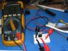
I got a couple of these in a kit recently. When I connected it to a battery it went poof and testing the schottkys one pack had a dead short on one side and good on the other and the second pack showed a diode voltage drop of .5V one side and ,2V the other.
Edit- The 2 packs were in a rectifyer pattern to rectify a pulse modulator coming through a secondary transformer wiring
When talking to the supplier they said these don't always read properly on a multimeter.

Now I am just wondering if this is BS or does it have a factual base?
 
Last edited:
When I connected it to a battery it went poof
To be expected if there wasn't a suitable current-limiting resistance in series.
one pack had a dead short on one side and good on the other and the second pack showed a diode voltage drop of .5V one side and ,2V the other.
Sounds like duff diodes.
Now I am just wondering if this is BS or does it have a factual base?
A DMM with a diode test function should give 'proper' readings. Expect a Schottky diode drop to be less than for a silicon diode.
 
I obtained some replacements today and tested them with a DMM .

A/ With negative on the common center terminal and the DMM set to diode checking I see a reading of .024 on both outside terminals

B/ With the positive on common I see . .38V rising to .40V

Now I don't understand what is happening here
I thought diodes conducted in one direction only B/ and with a voltage drop as it does so ? So why the reading in the other direction A/?
 
Sounds like more duff diodes :(
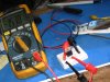
. Or else there's a flaw in your measuring arrangement (unlikely). I've just measured a Schottky with my DMM on its diode-test setting. I got readings of 345 in one direction and infinity in the other direction.
 
Anybody else have any opinions please ?
I'm about to go back to my supplier with this .
 
Anybody else have any opinions please ?
I'm about to go back to my supplier with this .

hi,
Do you have a datasheet or part type number for these diodes.??
 
SR1060 Eric

hi,
As you say, I would expect a forward drop of around 0.3V or so,when forward biassed and almost infinity when reverse biassed.
I would make a small test jig , see the image, and check the actual voltage drop across the diodes when forward biassed and reverse biassed.

This would check that your DVM on 'Diode' measure is working correctly.

Use your DVM on say DC volts setting around 2.5V or so.

Lets us know what you measure.

E.
 

Attachments

  • AAesp02.gif
    AAesp02.gif
    32.8 KB · Views: 175
I measure full voltage
When I swap the battery polarity I measure full voltage too?
Top clips are from battery-only ones moved
Bottom clips to DMM which is auto ranging
Resistor goes to center pin behind
Tried this on two of the new ones
 

Attachments

  • IMG_5211.JPG
    IMG_5211.JPG
    64.2 KB · Views: 170
  • IMG_5210.JPG
    IMG_5210.JPG
    68.3 KB · Views: 160
Last edited:
hi april,

It looks as though the diodes are either faulty or the wrong type number has been printed on them.

Where did you buy them.?

Eric
 
They were supplied in a kit eric and have been replaced and the ones tested are those replacements.
I don't want to name the supplier because they normally look after me pretty well and this is the first problem I have really had in over 20 years.I packed the whole kit up and mailed it back today.

I just needed to confirm what my DMM was telling me. Thanks for your help mate.
 
Last edited:
Status
Not open for further replies.

Latest threads

New Articles From Microcontroller Tips

Back
Top