Continue to Site

Welcome to our site!

Electro Tech is an online community (with over 170,000 members) who enjoy talking about and building electronic circuits, projects and gadgets. To participate you need to register. Registration is free. Click here to register now.

  • Welcome to our site! Electro Tech is an online community (with over 170,000 members) who enjoy talking about and building electronic circuits, projects and gadgets. To participate you need to register. Registration is free. Click here to register now.

Double check 2?

Status
Not open for further replies.

hjl4

Member
Ok, I know, my first post was sort of incomplete.

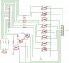
So I revised it a bit to see if anyone, as to get another opinion, can go over the schematic, and see if anything is wrong with it.

I build my own electronic circuits ect.. and program microchips, but this is my first
time trying to isolate the parallel port of a PC, with opto electronics.

I just need someone to confirm that everything is OK, before I purchase the parts for this.

The inputs are low voltage and only require resistors to isolate.
The outputs, are to control relays ect... and need to be isolated.

In this schematic, you'll quickly see which is which.
Thanks in advance. My first post had no replies, which leads me to beleive, no one is interested.
 

Attachments

  • opto_250.jpg
    opto_250.jpg
    121.3 KB · Views: 306
You thought no one was interested. You need to consider another possibility. Maybe everyone was waiting for someone else to answer. That's what I was doing. I am no parallel port expert. I can tell you what I can deduce from what you have presented.
You gave no resistor values, so I'm assuming you know what the current transfer ratio of the TIL193 is, and how to calculate the input current - including what the current drive capability of the parallel port is.
The outputs will rise to about 11.3 volts when you put a logic high on a port pin, assuming you don't have the emitter loaded too heavily. You will generally need some sort of pulldown resistor on each emitter if you want to guarantee that the emitter will return to 0V in a timely fashion. The emitters will probably not drive relays directly. Most relays require more current than the emitters can provide.
I can't comment on your inputs.
 
Thanks Ron H,

for at least replying to this post. For a moment there, I thought this was too much to ask. I'm on a dead line, and this is but a small fraction of the total project.

I am aware of the necessary resistors required, and mostly needed confirmation on the general principal of opto isolation.

As for the three relays, the optos will trigger, amplifing NPN transistors, which in turn will energize the relays ect...

Again thanks for stepping out.

Now I can move on.
 
Status
Not open for further replies.

Latest threads

Back
Top