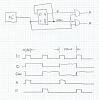
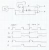
Continue to Site

Welcome to our site!

Electro Tech is an online community (with over 170,000 members) who enjoy talking about and building electronic circuits, projects and gadgets. To participate you need to register. Registration is free. Click here to register now.

  • Welcome to our site! Electro Tech is an online community (with over 170,000 members) who enjoy talking about and building electronic circuits, projects and gadgets. To participate you need to register. Registration is free. Click here to register now.

Does this work?

Status
Not open for further replies.

shortbus=

Well-Known Member
Most Helpful Member

Attachments

  • 2PhaseLogic..jpg
    2PhaseLogic..jpg
    2.5 KB · Views: 486
The picture is too small to see.
 
I don't know why it won't enlage? I'll try this
 

Attachments

  • 2PhaseLogic..jpg
    2PhaseLogic..jpg
    236.7 KB · Views: 362
It splits the input pulses so that each second pulse input is transfered to output A and the other half is transfered to B.

Reminds me about a demux, but it's not. I dont know how to possible use such a circuit. Nice if anybody having an idea how to use it :)
 
It will work as drawn.
 
neat. You're still playing around with memory devices and logic gates. Kinda ancient stuff, but cool too.

Take a close look at the main board of your PC. It's stuffed with ancient logic gates. :)
 
Take a close look at the main board of your PC. It's stuffed with ancient logic gates. :)


I wouldn't call the logic gates inside an FPGA on a motherboard ancient.
 
Last edited:
It splits the input pulses so that each second pulse input is transfered to output A and the other half is transfered to B.

Reminds me about a demux, but it's not. I dont know how to possible use such a circuit. Nice if anybody having an idea how to use it :)


I'm going to use it to make an Electrical Discharge Machine. This will allow me to turn on alternating mosfets to charge and discharge two capacitor banks. The capacitors will be connected to a shaped electrode to machine metal.
 
I was responding to Boncuk who mentioned a PC motherboard.

EDIT:
I've added a quote.
 
Last edited:
I dont know how to possible use such a circuit. Nice if anybody having an idea how to use it :)
Quote myself :D

I think if I where going to make a driver for a push-pull transformer with basic components (no µPC) then using this circuit would make sense. If adjacent pulses is of same duration, then it should resolve problems with unbalanced DC in transformer. Assuming changes over time won't affect this balance particularly.

I assume if the circuit is possible to expand, so that it split the input pulses out to three separate outputs- then it would make it pretty easy to do PMW on a reluctance motor.

I have redrawn the circuit. Looks pretty nice, doesn't it?
2plogic..png
 
Last edited:
Status
Not open for further replies.

Latest threads

New Articles From Microcontroller Tips

Back
Top