Electro Tech is an online community (with over 170,000 members) who enjoy talking about and building electronic circuits, projects and gadgets. To participate you need to register. Registration is free. Click here to register now.
Welcome to our site! Electro Tech is an online community (with over 170,000 members) who enjoy talking about and building electronic circuits, projects and gadgets. To participate you need to register. Registration is free. Click here to register now.
Hey all, I'm trying to build a circuit that when a laser beam focused on a photodiode is broken it sets off a timer to activate a relay for a few minutes, This is the design I'm working on but I 'm having problems, so does anyone have any suggestions
Hey all, I'm trying to build a circuit that when a laser beam focused on a photodiode is broken it sets off a timer to activate a relay for a few minutes, This is the design I'm working on but I 'm having problems, so does anyone have any suggestions
Which part are you having trouble with, the sensitivity of your beam detect? or generating one-shot minutes delay..? I would not use a 555 for minutes of delay. I am assuming the timing does not have to be accurate. I would use the 555 for a sloppy second counter maybe and then have that run a counting stage that can give you minutes. Some way to reset the stage will be needed.
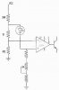
The photo diode normally operates under reverse bias and draws current when light falls on it, but it cannot make itself forward biased, which is what would have to happen for you circuit to work. I suggest you modify the circuit something like this:
Ratz! I put the diode backward, but otherwise its OK!
The sensing part of the circuit works fine(most of the time) its a problem with getting the timer to trigger for a few minutes, I'm using a cmos 555 so I thought there wouldn't be any problem with using large resistances to control the timer. I'm using a 100µF tantulum bead capacitor.
The sensing part of the circuit works fine(most of the time) its a problem with getting the timer to trigger for a few minutes, I'm using a cmos 555 so I thought there wouldn't be any problem with using large resistances to control the timer. I'm using a 100µF tantulum bead capacitor.
This type of capacitor is not good for timing purposes.
If you must use a 555 for long time intervals (not recommended), use a high quality capacitor (polystyrene etc..) that has low leakage. You will not be able to get very large values.. only say up to a few uF at most but then make your resistor very large to get the large RC.
Really, its not worth trying to use a 555 for anything, especially long delays. As suggested, have the 555 counting faster, and have it cascaded into a decade counter, or frequency divider.
dunno if this is something you want to consider, but many PICs have built in clocks...
p.s. - i assume you aren't trying to drive the relay directly from pin 3 of the 555...? Even though it can source alot of current, use a transistor and DON'T FORGET the feedback diode!
This site uses cookies to help personalise content, tailor your experience and to keep you logged in if you register.
By continuing to use this site, you are consenting to our use of cookies.