Continue to Site

Welcome to our site!

Electro Tech is an online community (with over 170,000 members) who enjoy talking about and building electronic circuits, projects and gadgets. To participate you need to register. Registration is free. Click here to register now.

  • Welcome to our site! Electro Tech is an online community (with over 170,000 members) who enjoy talking about and building electronic circuits, projects and gadgets. To participate you need to register. Registration is free. Click here to register now.

Does anyone else hate the pickit1 board as much as me?

Status
Not open for further replies.

kyussinchains

New Member
Hi,

I'm a total novice when it comes to embedded programming, I've been playing around with C for years, but never consistently, it seems I have to re-learn it all each time I come around to using it....

I've been given a microchip pickit1 flash starter kit with a pic12f675 onboard and I'm banging my head on a wall trying to make a single LED flash.... I can make two flash at once, but isolating a single one seems beyond me at the moment!

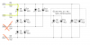
my problem is that the LEDs on the demo board are wired in a tri-state configuration and I don't seem to be able to set the pins in a high Z configuration. I'm using pin 3 to source the current for the LED, pin 2 to sink it, and setting pins 5 and 6 to input mode (High Z I believe)

my code is below:

Code:
#include <htc.h>

__CONFIG(UNPROTECT & BORDIS & MCLRDIS & PWRTEN & WDTDIS & INTIO);

void main()
{

	unsigned int i;

	TRISIO = 0b000011; //set GPIO0-3 as inputs, high Z
	ANSEL = 0x00; //clear ansel register
	CMCON = 0x07; //disable comparator

	while (1){ //loop continuously
		GPIO4 = 1; //set pin 3 high, LED on
		GPIO5 = 0; //set pin 2 low
		
		for(i = 0; i < 10000; ++i)
		{
			// do nothing, busy wait loop
		}

		GPIO4 = 0; //set pin 3 low, LED off
		GPIO5 = 0; //set pin 2 low
		
		for(i = 0; i < 10000; ++i)
		{
			// do nothing, busy wait loop
		}

		}
}

can anyone suggest why it's switching two LEDs on instead of a single one?

oh and I'm using MPLAB 8.10 and HI-TIDE 9.60

thanks in advance!
 
Looks like the schematic at
https://www.electro-tech-online.com/custompdfs/2009/01/PICKkitUserGuide.pdf

Your code should light LED DO only. Which are lighting ? You can tell the state and value for each of you IO bits by looking at the schematic and knowing which LEDs are conducting/on. If D0 and D2 are on RA2 is a low output rather then an input. If DO and D10 are on RA1 is a low output rather then an input etc.

You can also use a logic probe or volt meter to check that you can configure GPIO bits as you expect them.

After a quick look I did not see a problem with thecode.
It should NOT make a difference but try 0b00000011 as the value for TRISIO.

Is the board new or is it possible it has been modified.

At the very least tell us what LEDs are on. It will help soft out any software to hardware mapping problem.
 
my apologies, I should have said which LEDs are on!

the two that are on are D0 (the one I'm trying to light) and D2, I'll try the change to the TRISIO value out and let you know if it works after the weekend :)

The board isn't new, but as far as I can tell it's not been modified

thanks for the replies!
 
GPIO4 = 1; //set pin 3 high, LED on
GPIO5 = 0; //set pin 2 low

should be
Code:
                GPIO4 = 1; //set pin 3 high, LED on
		GPIO5= 0; //set pin 2 low
that should turn on D0
and turn off weak pullups
 
Last edited:
If D0 and D2 are on RA2 is a low output rather then an input. That is to say RA2 is providing a path to ground for LED D2.

The datasheet says weak pullups are active on power up and other resets. --11 -111 RA2 would need to be a low ouput to light D2, this should not be a problem. You could set WPU = 0x00 to be paranoid safe.

There are times when things that should not be problems are. Either due to misunderstanding or some quirk. For that reason the paranoid but safe way is best.

As I see it you need to figure out how RA2 is providing a path to ground D2

HTH
 
Bits are numbered 0 1 2 3 4 5 6 7

You need to trisate bits 1 and 2 which can be done with

Code:
TRISIO=0x000110

but instead you are doing

Code:
TRISIO=0x000011

which tristates bits RA0 and RA1 instead of RA1 and RA2.

It fits. We have all made this mistake :)

3v0
 
Last edited:
It's sinking down to RA2 I tried it. My ideal didn't work I figured make all pins output would stop it but it still sink to RA2 to turn on D2. If you source RA4 and sink RA5 D2 come's on to. If you make RA2 high to turn off D2 you lite 3 leds
 
I can flash the leds in a roll but it don't want to turn on just 1 lol I see why it would drive you cazy
 
I can flash the leds in a roll but it don't want to turn on just 1 lol I see why it would drive you cazy
It is not difficult. You can figure out which lines are hi low or tristated for each LED by looking at the schematic.
 

Attachments

  • charlieplex.png
    charlieplex.png
    65.6 KB · Views: 322
Last edited:
thanks for the help guys, I think we've cracked it, it annoys me that I left everything at work so can't test it before tuesday!

edit:
the next stage is to ask if you can alter the TRISIO value later in the code as I'm attempting to write a program to turn all the LEDs on in sequence, and it would be nice to be able to set different pins to input as and when they're needed to turn a specific LED on or off....
 
Last edited:
Yes you can.

I would put the TRIS and GPIO values for each LED into arrays. To turn on LED3 you

Code:
TRISIO=trisioArray[3];
GPIO = gpioArray[3];

Better yet define it as a macro or a function. With a small pic I would use the macro

Code:
#define LED_ON(n)  TRISIO=trisioArray[3];GPIO = gpioArray[3]

// to turn on LED2 use
LED_ON(2);

This is code written for the Junebug which has 3 switches and 6 charlieplexed LEDs. It may be of interest.

Code:
// ADVANCED COMPUTER SCIENCE  9/23/2008
// DEMO PROGRAM
//
// Name:    read switches
// Purpose: demostrate how to read switches and the 
//          use of arrays to operate the LEDs
//
//

// settings for configuration memory
#pragma	config OSC = INTIO2, WDT = OFF, LVP = OFF

// processor definitions
#include <p18f1320.h>

// tell the compiler these are unsigned 8 bit 
// constants that can be stored in flash with 
// the program code. 
          
rom const unsigned char lataVal[] = 
          {0x01,  0x40, 0x40, 0x80, 0x80, 0x01};
          
rom const unsigned char trisaVal[] = 
          {~0x41,~0x41,~0xC0,~0xC0,~0x81,~0x81}; 

void main(void)
{
  unsigned char sw;
  unsigned char btn1;
  unsigned char btn2;
  unsigned char btn3;
      
  // crank up the internal clock to 8MHz
  OSCCONbits.IRCF0=1;   
  OSCCONbits.IRCF1=1;
  OSCCONbits.IRCF2=1;
 
  ADCON1=0x70;        // all digital
  TRISB=0x25;         // Switches on RB0 RB2 RB5 
  // PORTB weak pullups for switches
  INTCON2bits.RBPU=0; 


  while(1)
  {
    // Read from PORTB, 
    // what would happen if used 
    //'sw=PORTB&0x25' instead ?
    // Use PORTB not LATB with weak pullups.
    sw=PORTB;
    // deterimine if any was pressed
    btn1 = (!(sw & 0x01));  // RB0
    btn2 = (!(sw & 0x04));  // RB2
    btn3 = (!(sw & 0x20));  // RB5
    
    // turn on correct LED if switch was pressed
    if(btn1)  // why do we not use "if(btn1==1)" ?
    {
      LATA=lataVal[0];
      TRISA=trisaVal[0];
    }
    if(btn2)
    {
      LATA=lataVal[1];
      TRISA=trisaVal[1];
    }
    if(btn3)
    {
      LATA=lataVal[2];
      TRISA=trisaVal[2];
    }
  }
}
 
Ok I'm going to stay away from C . Here how to Bink 1 led on the pickkit1 in assembly

Code:
	list p=12f675
	include "p12f675.inc"
__CONFIG _CPD_OFF & _CP_OFF & _BODEN_OFF & _MCLRE_OFF &_PWRTE_OFF & _WDT_OFF & _INTRC_OSC_NOCLKOUT
#define	BANK1		banksel 0x80	;Select BANK1
#define	BANK0		banksel 0x00	;Select BANK0

 cblock 	0x20 			;start of general purpose registers
		count1 			;used in delay routine
		counta 			;used in delay routine 
		countb 			;used in delay routine
	endc
	
	org	0x0000			;org sets the origin, 0x0000 for the 12f675,
main	
	call    0x3FF      ; retrieve factory calibration value
					
	BANK1					  
	movwf   OSCCAL      ; update register with factory cal value 

	BANK0
	clrf	GPIO		;Clear Port
	BANK1
	clrf	ANSEL		
	movlw	0xFF
	movwf	TRISIO		;Tri-State All Inputs
	clrf	VRCON		;Vref Off
	BANK0				
	movlw	0x07		
	movwf	CMCON		;Comparator Off	

start:
	 bsf     STATUS,RP0       ; select Register Page 1
         bcf     TRISIO,4          ; make IO Pin C0 an output
	 bcf	 TRISIO,5
	 bcf     STATUS,RP0       ; back to Register Page 0
         bsf     GPIO,4          ; turn on LED C0 (DS1)
	 call	 Delay			;this waits for a while!
	 clrf	 GPIO         ;turn off led
	 call	 Delay			;this waits for a while! 
         goto    start                ; wait here
	
Delay	movlw	d'250'			;delay 250 ms (4 MHz clock)
	movwf	count1
d1	movlw	0xC7
	movwf	counta
	movlw	0x01
	movwf	countb
Delay_0
	decfsz	counta, f
	goto	$+2
	decfsz	countb, f
	goto	Delay_0

	decfsz	count1	,f
	goto	d1
	retlw	0x00
	
	end
Don't like C
 
Last edited:
This is in mikroC it flashes the 1 led
Code:
void init_ports(void) {
   TRISIO = 0B00001111; // set as output
}

void main() {

   init_ports();
   
   while(1) { // infinite loop
   
      GPIO = (1<<4);
      delay_ms(200);
      
      GPIO = 0;
      delay_ms(200);
  }
}
I don't use C much I couldn't get the delay to work with HI-Tech
I guess I have to buy it to use delay_ms works good in mikroC
 
Last edited:
Well I tried one more time with HI-tech C
and got your code to work
Code:
include <htc.h>

__CONFIG(UNPROTECT & BORDIS & MCLRDIS & PWRTEN & WDTDIS & INTIO);

void main()
{

	unsigned int i;

	TRISIO = 0b001111; //set GPIO0-3 as inputs, high Z
	ANSEL = 0x00; //clear ansel register
	CMCON = 0x07; //disable comparator

	while (1){ //loop continuously
		GPIO4 = 1; //set pin 3 high, LED on
		
		for(i = 0; i < 10000; ++i)
		{
			// do nothing, busy wait loop
		}

		GPIO4 = 0; //set pin 3 low, LED off
		for(i = 0; i < 10000; ++i)
		{
			// do nothing, busy wait loop
		}

		}
}
this flashes just D0
 
Last edited:
thanks for the help guys, I'm in the middle of moving house at the moment and had to take an extra day off work yesterday to pack stuff, so I didnt get a chance to try the new code until today.

Suffice to say it worked, it was a simple case of setting the TRISIO register value to 0b000110 instead of 0b000011

then I had a play around lighting LEDs in sequence and thanks to the examples provided by 3v0, I now have a nice small piece of code which lights all 8 LEDs in sequence, just in case you're interested, I'll post it up here

Code:
#include <htc.h>

__CONFIG(UNPROTECT & BORDIS & MCLRDIS & PWRTEN & WDTDIS & INTIO);


const unsigned char TrisIOArray[] = 
{0b000110, 0b000110, 0b100010, 0b100010, 0b010010, 0b010010, 0b110000, 0b110000};
//Array containing all neccessary TRSIO register values

const unsigned char GpioArray[] = 
{0b010000, 0b100000, 0b010000, 0b000100, 0b100000, 0b000100, 0b000100, 0b000010};
//Array containing all neccessary GPIO register values

#define LED_ON(n)  TRISIO=TrisIOArray[n];GPIO = GpioArray[n] //define LED_ON() macro

void main()
{

	unsigned int i;
	unsigned int n;

	ANSEL = 0x00; //clear ansel register
	CMCON = 0x07; //disable comparator

	while (1){ //loop continuously
		
		for(n = 0; n < 8; n++) //cycle through the array values from 0-7
		{
		LED_ON(n); //call LED_ON() macro, assign variable n to it	
		
		for(i = 0; i < 10000; i++)
		{
			// do nothing, busy wait loop
		}
		}

		}
}

once again thanks for giving me that little push to get something started!!
 
unfortunately I'm now stuck again.....

I'm trying to read an input into the device (namely the pushbutton connected to GPIO3)

my initial idea was for the delay to decrease when the button is pushed, however I found that the light sequence worked as before but when the button was pushed, the sequence would stop and a single LED would remain lit.

At the suggestion of a friend, I replaced the switch input with a variable which increments every time an LED is switched on, when it hits 20 or so, the decreased delay is implemented. However this gives the same effect, it works fine until it tries to switch to the faster delay, then a single LED switches on and I have to power cycle the device to get it moving again.

here is the code:
Code:
#include <htc.h>

__CONFIG(UNPROTECT & BORDIS & MCLRDIS & PWRTEN & WDTDIS & INTIO);


const unsigned char TrisIOArray[] = 
{0b000110, 0b000110, 0b100010, 0b100010, 0b010010, 0b010010, 0b110000, 0b110000};
//Array containing all neccessary TRSIO register values

const unsigned char GpioArray[] = 
{0b010000, 0b100000, 0b010000, 0b000100, 0b100000, 0b000100, 0b000100, 0b000010};
//Array containing all neccessary GPIO register values

#define LED_ON(n)  TRISIO=TrisIOArray[n];GPIO = GpioArray[n] //define LED_ON() macro

void main()
{

	unsigned int i;
	unsigned int n;
	unsigned int j = 0;

	INTCON = 0;						//disable interrupts
	ANSEL = 0x00; 					//clear ansel register
	CMCON = 0x07; 					//disable comparator

	while (1){ 						//loop continuously
		
		for(n = 0; n < 8; n++) 		//cycle through the array values from 0-7
	
		{
			LED_ON(n); 				//call LED_ON() macro, assign variable n to it	
			j++;					//increment j every time loop runs
			if (j <= 20)			
			for(i = 0; i < 10000; i++)
		{
									// do nothing, slower busy wait loop
		}
			else
			for(i = 0; 1 < 5000; i++) 
		{
									// do nothing, faster busy wait loop
		}
		}
	
		}
}

any suggestions?
 
Look more closely at your code,

Code:
        for(i = 0; [COLOR="Red"]1[/COLOR] < 5000; i++)
:eek::eek:

Mike.
 
Status
Not open for further replies.

Latest threads

New Articles From Microcontroller Tips

Back
Top