Continue to Site

Welcome to our site!

Electro Tech is an online community (with over 170,000 members) who enjoy talking about and building electronic circuits, projects and gadgets. To participate you need to register. Registration is free. Click here to register now.

  • Welcome to our site! Electro Tech is an online community (with over 170,000 members) who enjoy talking about and building electronic circuits, projects and gadgets. To participate you need to register. Registration is free. Click here to register now.

Does anybody knows what is the part of the circuit and its function?

Status
Not open for further replies.

Harros

New Member
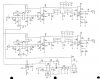
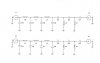
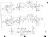
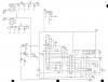
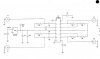
Hi guys, I am now building a RF amplifier, and I have the sample circuit as a reference. However, I wonder what one of the part of the circuit is... (I guess its a bandpass filter) i am sorry for my limited knowledges in electronics... Does anyone here have clues with this part of circuit?? Thank you!!!
 

Attachments

  • unknown.jpg
    unknown.jpg
    105.7 KB · Views: 227
I'd agree with Nigel that it's a tuned circuit, crystal, ceramic or possibly other. If you knew what was supposed to happen that would help narrow the possibilities. Example: if this happened to be the 1st IF of a superhet radio you might expect the frequency of the filter to be the sum or difference of the frequency being rec'd and the oscillator. What you won't know is how selective it's supposed to be - but you could guess at a range dependent on what you intend to actually do with it.
 
stevez said:
I'd agree with Nigel that it's a tuned circuit, crystal, ceramic or possibly other. If you knew what was supposed to happen that would help narrow the possibilities. Example: if this happened to be the 1st IF of a superhet radio you might expect the frequency of the filter to be the sum or difference of the frequency being rec'd and the oscillator. What you won't know is how selective it's supposed to be - but you could guess at a range dependent on what you intend to actually do with it.

This circuit part is a IF amplifier, I think, as there are two BJT amplifier cascaded with the bandpass filter.
 
Harros said:
This circuit part is a IF amplifier, I think, as there are two BJT amplifier cascaded with the bandpass filter.

From the small section of circuit it's impossible to say what it is, although an IF amplifier is a possibility - we need the rest of the circuit to tell.
 
Nigel Goodwin said:
From the small section of circuit it's impossible to say what it is, although an IF amplifier is a possibility - we need the rest of the circuit to tell.

Well, this is the entire circuit of it. By the way, this is the circuit of one of the module in the system...
 

Attachments

  • entire circuit.JPG
    entire circuit.JPG
    68.1 KB · Views: 160
That's a bit better, but it still gives no clue as to what it is, or what frequency it might be working at - it appears to be a common LO feeding two mixers, followed by two filtered amplifiers. With the filters either been one crystal filter, or two ceramic ones in series.

Presumably it's still only part of a complete circuit?, which is why it doesn't tell enough.
 
Nigel Goodwin said:
That's a bit better, but it still gives no clue as to what it is, or what frequency it might be working at - it appears to be a common LO feeding two mixers, followed by two filtered amplifiers. With the filters either been one crystal filter, or two ceramic ones in series.

Presumably it's still only part of a complete circuit?, which is why it doesn't tell enough.

These are all the circuit parts in the receiver part of the design, but I am thinking of removing the mixers and the DDS in my design as my project is still in testing stage.

P/S: This system is the Near Field Electromagnetic Ranging system
 

Attachments

  • PreselectFilter.JPG
    PreselectFilter.JPG
    24.3 KB · Views: 139
  • IFAmp.JPG
    IFAmp.JPG
    70.4 KB · Views: 143
  • Converter.JPG
    Converter.JPG
    58.4 KB · Views: 149
  • PhaseDetector.JPG
    PhaseDetector.JPG
    31.1 KB · Views: 146
The original section is a filter.

The three items labeled X1, X3, and X5 have not DC signal going to them as they are only connected by C18 and C32. That makes it just about impossible for it to usefully contain any semiconductors.

"X" is a common circuit abreviation for crystal, and it has also spread to crystal oscillators and crytal filters.

I think that makes them monolythic crystal filters, which are crystals with the electrode on one side separated into two halves. The two halves are only coupled when the crystal resonates.

They could also be crystal filters, which are assemblies of passive components and crystals, tuned to only couple at certain frequencies.
 
Status
Not open for further replies.

Latest threads

New Articles From Microcontroller Tips

Back
Top