Continue to Site

Welcome to our site!

Electro Tech is an online community (with over 170,000 members) who enjoy talking about and building electronic circuits, projects and gadgets. To participate you need to register. Registration is free. Click here to register now.

  • Welcome to our site! Electro Tech is an online community (with over 170,000 members) who enjoy talking about and building electronic circuits, projects and gadgets. To participate you need to register. Registration is free. Click here to register now.

Do you know this potentiometer?

Status
Not open for further replies.

2PAC Mafia

Member
Hello,

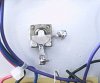
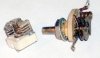
this is a potentiometer I have to replace because its resistence is not changing. I always have 1K but I don´t know its original value, I guess it would be a 1K poti and now is showing always its maximum value. It´s strange because it doesn´t seem the usual poti, on this one you can see the metal plate moving (sliding) when you move the control. I have compared the complete movement and seems to be shorter than a normal 1 turn poti, so if I fix a normal 1K one will not match with the scale already marked on the front plate of the device, do you know where to find this strange potis?

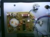
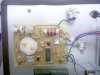
On the same device there are three more potis with some metal plates, one the other up to 5 or 6 metal plates and then the common plates which slides onto them...
 

Attachments

  • potenci_metro_lubri-sensor_de_bp_solo_poti.jpg
    potenci_metro_lubri-sensor_de_bp_solo_poti.jpg
    33.9 KB · Views: 709
Two things come to mind - the pot has failed or it's a variable capacitor. The variable capacitor ought to show very high resistance - if otherwise it is has probably failed.
 
Looking at the picture and reading your description of metal plates which move between other metal plates, this is not a variable resistor but a variable capacitor.

Your picture shows only two connections to the "thing", which also makes me think that it is a capacitor, not a resistor.

Can you show another picture of the side of the thing?

JimB
 
Here are some Examples of Variable Capacitors.

I Believe this is What you have.

If you Disconnect them from the Circuit, they should measure Infinative Resistance. Definately NOT a Low Resistance.

They are Properly Measured with a Capacitance Meter.

I Would Suspect from your Picture that the one you show is about 10 or 20 pF.
 

Attachments

  • variable-caps.jpg
    variable-caps.jpg
    42.9 KB · Views: 672
Hello,

sorry but I also wanted to tell you what you already thought, because after removing the wires I measured again and I didn´t reach any resistence, that gave me also the idea about a variable capacitor. I´ve had problems with Internet and I couldn´t tell you.

Are these capacitors using the air as dielectric?

Yes Chemelec, it has those plates, how can I check if it is failing and the real value if it wouldn´t show no capacitance value? I don´t have capacitance meter to those values I guess. I think the failure is that because when you move the control nothing is moving on the analogue gauge on the device.

Another doubt I have is that there is another one also used for calibration but this one is only connected to the PCB by one wire, the other pin at the capacitor is free, what sense has that with only one cable connection???
 
Hello,

here you can see also the PCB where the capacitors are connected, you can see on the top right side one capacitor has only one wire connection to the PCB. What do you think could be the failure at this PCB?
 

Attachments

  • pcb_lubri-sensor_bp.jpg
    pcb_lubri-sensor_bp.jpg
    462.1 KB · Views: 670
I Assume the Case is Metal?

The Unused Terminal is Also Connected to the Shaft that goes to the knob and the Nut to hold it in place.
If that mounting Shaft is bolted to a Metal Case, that is the other wire.

As Long as there is Always Infinitive Resistance across the Capacitor, as you turn the knob, it is Probably OK. There is Not much that goes wrong with these caps. (Unless you Bend the Plates so it Shorts out.)

Without Knowing What this device is, and ALSO Seeing a Schematic of it, It is Impossible to really tell you much more.

Just because the Analogue Gauges don't change when you turn those caps, That could be any one of a Thousand Different problems. But Probably Not those Caps.
 
I Lightened it up so I could see it better.

Why do you have one of those Vari-caps Disconnected?

This is obviously a High Frequency Circuit and You can do a lot of damage playing around like that.

Have you Checked the supply Voltages?

Possibly that Transistor?

What is that IC?
 

Attachments

  • lubri-sensor.jpg
    lubri-sensor.jpg
    139.7 KB · Views: 643
You can actually determine the approximate value of it.

Just select an oscillator that runs at a low frequency. It has to be low enough so that you hear thumps instead of a solid tone.

Look for any capacitors that contribute to the frequency.

Or better yet, make your own out of a 555 timer.

Once you found the capacitor, connect your trim capacitor in parallel with the other one.

If all the noise stops completely, then your trim capacitor is not functioning properly. Now as you turn the trim cap, the speed of the thumps change.

Using the approximate equation: T = R * C, you can determine the time by counting the seconds between the thumps, the resistance is already given, and the capacitance is equal to the capacitor already in the oscillator and the value of the trim capacitor.

If you don't notice much of a change, lower the capacitance, and increase the resistance.
 
MStechca,
A trim capacitor of only about 20pF won't have any affect on a low frequency 555 oscillator.
 
I think alot of variable capacitors use thing sheets of plastic as dielectric.

To verify that it is working, you could solder it across the variable capacitor in any cheap radio and turn it. This should cause the station to change.
 
zachtheterrible said:
To verify that it is working, you could solder it across the variable capacitor in any cheap radio and turn it. This should cause the station to change.

You can simply check if it's faulty with a multi-meter and a pair of eyeballs (or even one?). See if it's S/C with the meter, and see if it's physically broken with the eyeballs - there's nothing much else to go wrong with an air spaced variable capacitor.
 
Hello,

I Assume the Case is Metal?

The Unused Terminal is Also Connected to the Shaft that goes to the knob and the Nut to hold it in place.
If that mounting Shaft is bolted to a Metal Case, that is the other wire.

As Long as there is Always Infinitive Resistance across the Capacitor, as you turn the knob, it is Probably OK. There is Not much that goes wrong with these caps. (Unless you Bend the Plates so it Shorts out.)

Without Knowing What this device is, and ALSO Seeing a Schematic of it, It is Impossible to really tell you much more.

Just because the Analogue Gauges don't change when you turn those caps, That could be any one of a Thousand Different problems. But Probably Not those Cap

Yes the case is metal and the free pin makes contact to the case throught the bolt. That is also ground from the other capacitor where we have the negative wire from the 9V battery.

Sorry but I don´t have a drawing and I think this device is used to test the oil, I guess it tests the water quantity in the oil but I´m not 100% sure. I still didn´t check a lot of things there, I´ll try to do it today, may be there is no oscillation signal... I will test with the scope.

I Lightened it up so I could see it better.

Why do you have one of those Vari-caps Disconnected?

This is obviously a High Frequency Circuit and You can do a lot of damage playing around like that.

Have you Checked the supply Voltages?

Possibly that Transistor?

What is that IC?

I disconnected that Vari-cap to measure it because I got a measurement of 1K if it was connected.

I only checked the battery and then the 78L05 on the PCB, the voltages there are right.

I still didn´t check the transistor or the IC which is a 7400.
 
Hello,

I still don´t know the reason but I think the problem now is solved. The failure was that when you turn the central knob in theory you could adjust the indicator on a microamperemeter gauge (-50 to +50 uA) but always when you turned it nothing happened.
I checked that on the vari-cap we received a voltage signal but I couldn´t see it very well with the scope. Then I tested everything again but with the metal plate removed from the case and I saw it worked, I could adjust it.
But when I put again the four screws to fix the frontal metal plate again on the case I saw it failed again. It couldn´t be any derivation because I already checked that the case itself was the negative but when I pressed with my fingers on the metal plate the indicator was going to "0" again and when I released to the proper indication. It was like the microamperemeter itself had some distorsion or loose the signal when I pressed on the metal plate. I removed the microamperemeter from the metal plate and I installed it again but still without knowing the reason it works OK.
 
Status
Not open for further replies.

Latest threads

New Articles From Microcontroller Tips

Back
Top