Hello To Everbody
I came accross a diy usb controller / display circuit.
Its current firmware is described as:
appears as 32 button game device
26 standard pushbuttons & 4 rotary encoders.
7-segment & up to 40 leds or 14/16 segment & up to 32 leds
Aftermarket RPM gauges
I have constructed the circuit & programmed the chip all ok.
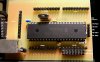
When connected to windows it displays as diy usb button box under the game controllers icon in the control panel. But with the limited info on the device & my limited knowledge, i am stuck with the pin outputs of the controller. I would love to connect a 7-segment display & some leds to display rpm limit on the device. I have tried to disassemble the hex file & try to unstand how the controller has been ported, but again my limited knowledge of anything to do with programming left me with a sore head & more question than i could find answers for, so its time to ask for some expert help. I have attatched the two hex files for the controller, used to programme the chip (PIC18F4550). There is also a jpg of the board & the pin layout, plus a circuit diagram.
Any help on this would be great thanks for taking the time to read my post.
I came accross a diy usb controller / display circuit.
Its current firmware is described as:
appears as 32 button game device
26 standard pushbuttons & 4 rotary encoders.
7-segment & up to 40 leds or 14/16 segment & up to 32 leds
Aftermarket RPM gauges
I have constructed the circuit & programmed the chip all ok.
When connected to windows it displays as diy usb button box under the game controllers icon in the control panel. But with the limited info on the device & my limited knowledge, i am stuck with the pin outputs of the controller. I would love to connect a 7-segment display & some leds to display rpm limit on the device. I have tried to disassemble the hex file & try to unstand how the controller has been ported, but again my limited knowledge of anything to do with programming left me with a sore head & more question than i could find answers for, so its time to ask for some expert help. I have attatched the two hex files for the controller, used to programme the chip (PIC18F4550). There is also a jpg of the board & the pin layout, plus a circuit diagram.
Any help on this would be great thanks for taking the time to read my post.