Continue to Site

Welcome to our site!

Electro Tech is an online community (with over 170,000 members) who enjoy talking about and building electronic circuits, projects and gadgets. To participate you need to register. Registration is free. Click here to register now.

  • Welcome to our site! Electro Tech is an online community (with over 170,000 members) who enjoy talking about and building electronic circuits, projects and gadgets. To participate you need to register. Registration is free. Click here to register now.

DIY Metal detector

Status
Not open for further replies.

acko1989

New Member
Hi,

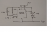
I have questions about this 555 metal detector circuit in attachment down below. I understand that this works in astable mode and the induction of a coil changes when there is metal near by, so frequency changes. My question is: Why is one side of inductor and resistor connected to output (Pin 3) of 555 timer?
 

Attachments

  • metal detector.png
    metal detector.png
    145.2 KB · Views: 133
Last edited:
It's using the high and low threshold inputs only, no "reset" as with the more common 555 arrangement.

As an oscillator it works like a simple schmitt trigger R-C type, such as on this page:


The output only changes when the input reaches about 2/3 supply as the capacitor voltage rises, then changes the opposite way when the cap voltage drops to around 1/3 supply.

The out switches opposite to the input, so as soon as it eg. reaches the high threshold the output switches low and the voltage starts dropping again.

The 555 version has much higher output current capability so it can also drive a loudspeaker.

The coil inductance will change with proximity to metal so could vary the frequency to some extent by changing the feedback.
 
Is capacitor discharged only through 47k ohm resistor?

Yes, the circuit operation is symmetrical.

If the capacitor voltage is below 1/3 supply, the output switches high and the capacitor starts to charge through the resistor.

When the cap voltage passes 2/3 supply, the output switches low and the capacitor discharges through the resistor.
And repeat..

It's a slightly less common setup with a 555, but extremely common with schmitt trigger oscillators using sections of logic ICs like in the earlier link.
 
Many thanks!

You say that circuit operation is symmetrical. Does this mean that capacitor is charged ONLY through 47k ohm resistor?
May I ask how exactly LC part of this circuit effect output frequency to the speaker?
 
The above circuit is symmetric because the cap is Charged and Discharged through the same resistor ... ack01989 ... the LC in parallel with the 47k has an influence on the Charge and Discharge rate therefore affecting the output frequency.

Here is a variation of that circuit without the LC .... just a straight RC oscillator

One thing to take note with that circuit above from the OP is that it may also be sensitive to supply voltage. So if you are looking for consistency I would search for another circuit.... an emitter coupled oscillator is good (In my opinion), but you will likely need to divide your frequency way down by a few orders of magnitude for it to be audible. (binary ripple counter 4040B or similar)

Emitter Coupled Oscillator Reference:

Note:
Instead of using the output in the image link above, use a third transistor (NPN 2n3904) and tie the BASE to the T1 & T2 emitter from the image, The Emitter of the NPN goes to ground where the Collector is pulled up to your supply voltage with a 1k resistor. The OUTPUT is the junction between the Collector and the 1k resistor of the NPN transistor.

R1 = 1k in the image link above. T1 and T2 can be 2n3906, in fact all transistors can be general purpose generic.
 
The simple circuit here has demos on Google - You Tube. It barely changes the frequency even when a huge iron is place right on the coil.
A real Metal Detector uses a Beat Frequency oscillator with two same-frequency oscillators but only one oscillator has the sensing coil. It is very sensitive.
 
Status
Not open for further replies.

Latest threads

New Articles From Microcontroller Tips

Back
Top