Continue to Site

Welcome to our site!

Electro Tech is an online community (with over 170,000 members) who enjoy talking about and building electronic circuits, projects and gadgets. To participate you need to register. Registration is free. Click here to register now.

  • Welcome to our site! Electro Tech is an online community (with over 170,000 members) who enjoy talking about and building electronic circuits, projects and gadgets. To participate you need to register. Registration is free. Click here to register now.

disposable camera transformer

Status
Not open for further replies.
Probably internally shorted. If a transformer is gradually overloaded to failure it would make sense that it's one of the winding in the middle of the transformer where the heat is most intense.


so much trouble for nothing........

thanks guys.
 
Just stumbled on this today. Some interesting things with camera flash & Joule Thief...
Might help some on the transformer. Don't know why you are sweating over it anyway. You can get them free, if you ask around places that process the film (got 17 from the third place I asked). $1- $2.00/board at several surplus sites.
 
ok... finally i got one transformer that looks like it's fine and measures right!

the output coil is 210ohm can somebody tell me what's the output voltage and current if i give it 3V using an oscillator circuit? i don't know what frequency i'm going to use, but i want to get about 500V from it.
 
Last edited:
The resistance of the secondary does not tell you anything. The output voltage depends on the "turns ratio" - the number of turns on the primary compared to the number of turns on the secondary and this can only be applied when the transformer is used in a sinwave application and not in flyback mode.
You will have to try it and see. It is generally 350v when using a 1.5v supply and way over 800v when using 3v supply.
 
Typical inverters like this use audio frequencies. 1-50khz generally. You need to know your operating frequency to test it properly. I would say 10khz is a good place to start. You can use an audio power amp and a PC sound card to generate a 10khz sine wave and compare the incoming and outgoing voltages to get your turns ratio. This may not work if the primary coil's resistance is less than 4 ohms. Note you need an osciliscope to test this as even good AC meters don't generally go above a few khz I don't think.
 
The frequency of the circuit will be anything between 50kHz and 150kHz and this will primarily depend on the impedance of the transformer. You really need to use the transistor supplied with the transformer as it is a high-gain high-current type. The circuit relies on the impedance of the transformer (and the type of transistor) to produce the frequency of operation as no timing capacitor is used in many of these circuits.
It is really a very sophisticated circuit and for $1.50 you can get a whole camera from a photo shop.
 
I'd be more inclined to use a micro controller or 555 circuit to control the pulses going through the primary, if you can control the duty cycle and frequency independent of the components you have a lot more control over the final charge. If you've ever noticed the increasing pitch from these charge circuits you'll realize that they start at lower audio and as the load decreases (capacitor becomes charged) gets up to the natural resonance of the transformer/transistor combo, I'm not sure how much of this comes from harmonics rather than the primary frequency but cap charge circuits are pretty noisy.
 
i'm going to use a 555 if the transistor is not sufficient.

here's a diagram
 

Attachments

  • Photo%20Flash%20Psu.JPG
    Photo%20Flash%20Psu.JPG
    19.6 KB · Views: 365
You cannot use a 555 or any external input as you cannot get the correct timing.
The circuit is much more sophisticated than that.
 
That particular circuit maybe colin, but it's not because it's too sophisticated, it's because it's too simple, it's operation is completely dependent on the inherent parameters of the components that make it. It could easily be modified to allow the primary to be driven by a 555
 
Try to use a 555. You have absolutley no idea of the timing of the pulse and unless you produce the same pulse-width, the output will be totally differerent to the original circuit. You will either be over-saturating the transformer and drawing far too much current with a pulse that is too wide, or the output will be much lower than the original if the width is too small.
Plus the transistor used in the original design has a current capability of about 800mA and saturates to less than 0.2v. A 555 is useless. I have tried to drive these transformers. You can't.
 
Last edited:
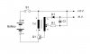
Right colin, which is why you tune the 555 pulse width and frequency. I didn't say it was a plug in replacement. It's better than being a slave to the circuit though and you can adjust the output with a wide variety of input voltages. You don't use the 555 to drive it directly that would be silly, you use the 555 to drive a transistor to drive the primary coil. While you say 'sophisticated' I would classify that circuit as being single purposed and inflexible, and as I said personally I would use a micro controller and analog comparators to control things.
 
Last edited:
Why don't you just put a transistor on the primary and connect the feedback winding and you won't have any problems trying to detemine any of the characteristics.
 
Why don't you just put a transistor on the primary and connect the feedback winding and you won't have any problems trying to detemine any of the characteristics.


as i said and as the schematic shows...that's what i'm going to try first... and i think a 2N2222 it's suitable because it has high enough gain and current.
 
2222 is quite unsuitable. It is only 200mA CE current. You will find the transistor used in this application is 800mA. It is a really high current requirement. That's why I said: there's more to it than first meets the eye.
 
Last edited:
Status
Not open for further replies.

Latest threads

Back
Top