Electro Tech is an online community (with over 170,000 members) who enjoy talking about and building electronic circuits, projects and gadgets. To participate you need to register. Registration is free. Click here to register now.
Welcome to our site! Electro Tech is an online community (with over 170,000 members) who enjoy talking about and building electronic circuits, projects and gadgets. To participate you need to register. Registration is free. Click here to register now.
Is there an easy way to display voltage range from 0-12, or 6-12, using a 10 bar LED? The LM3914 seems to be archaic, and a bit of a hassle to combine with a separate LED bar.
Doesn't someone make a single part that combines the LED bars with the IC?
LM391X is pretty much the picture of simplicity ... if that's not complicated enough, you could program the A2D portion of a microcontroller into driving a LED bargraph
looking at the example in the lm3914 datasheet, I count 5 components, including the led graph, the ic, an optional capacitor and two resistors.
Is there an easy way to display voltage range from 0-12, or 6-12, using a 10 bar LED? The LM3914 seems to be archaic, and a bit of a hassle to combine with a separate LED bar.
Doesn't someone make a single part that combines the LED bars with the IC?
Certainly at one time you could buy LM3914's incorporated into an LED bar, using COB (Chip On Board) technology - but I can't say I've looked for them at all recently!.
Talking about archaic things, I still have some of National's modules with an LM3915 driving the dimmest LED bargraph that I've seen. Under the cover for the LEDs I see that very small LEDs are welded, not soldered to the pcb. I was thinking about drilling them out and replacing the LEDs with modern much brighter LEDs but it is too much trouble.
Is there an easy way to display voltage range from 0-12, or 6-12, using a 10 bar LED? The LM3914 seems to be archaic, and a bit of a hassle to combine with a separate LED bar.
Doesn't someone make a single part that combines the LED bars with the IC?
Certainly at one time you could buy LM3914's incorporated into an LED bar, using COB (Chip On Board) technology - but I can't say I've looked for them at all recently!.
They were NSM3914, NSM3915 and NSM3916.
A one point in time, National sold the manufacturing rights of these parts to another company. I Believe it was called "Ten-4 Electronics"
Shortly thereafter, they were completely discontinued by that company.
Certainly at one time you could buy LM3914's incorporated into an LED bar, using COB (Chip On Board) technology - but I can't say I've looked for them at all recently!.
using the SOIC flavor of the LM3914, smt resistors and smt LEDs, along with a pcb, you could fit all the parts in a footprint about the same (or smaller) as an regular DIP LED bar graph
I just suggested surface mount since the OP apparently is concerned about space, wanting an entire voltage readout solution no bigger than a 20 pin DIP
I just suggested surface mount since the OP apparently is concerned about space, wanting an entire voltage readout solution no bigger than a 20 pin DIP
Thanks.
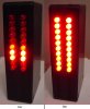
I had to use Veroboard on a diagonal to fit my project's LEDs tight together. I had to file a few of the LEDs' shoulders a little to make them fit. The display board and the electronics board interlock so the display board is secured without screws.
The bottom 1/3rd of the box houses a little "9V" Ni-Cad battery that lasts only about 20 minutes if all 20 LEDs are at their max 26mA brightness, and the box gets a little warm. It lights up a medium sized room at night. :lol:
The outputs of the microcontroller and the transistors are driving the LEDs. The grid is arranged so that each of the 20 LEDs or any number of LEDs can be lighted by using only 5 signal wires, since the microcontroller has only a few pins.
I still don't see how this works. With 5 wires, there's 32 combinations. With just 10 LEDs there are 1024 possible lighting combinations. Does anyone have a link to define "charieplexing"?
The grid doesn't provide thousands of light patterns, only 20 as a dot, or you figure it out for a bar that goes from no LED lighted to all 20 lighted.
It might also have a dot on one side with 10 LEDs and as a bar on the other side with the remaining 10 LEDs.
I still don't see how this works. With 5 wires, there's 32 combinations. With just 10 LEDs there are 1024 possible lighting combinations. Does anyone have a link to define "charieplexing"?
I apologize... I didn't mean to confuse you... Google "charlieplexing" and you'll come up with several hits...
Charlieplexing, also known as N(N-1) multiplexing, is a Maxim term... It takes advantage of an I/O pins ability to sink current (output 0), source current (output 1), or become high impedance (input) where it neither sources or sinks current... It provides a nifty mechanism for driving matrixed LEDs or reading matrixed switches with a minimun number of I/O pins... In this case you can light one to twenty LEDs in any order and if you implemented PWM control you could also provide 16 or 32 different light levels for each individual LED...
For your particular project you could use 4 pins to drive a 10 LED matrix and then use an Analog-to-Digital input pin to measure the voltage... The program in the little 8-pin microcontroller would measure the voltage and drive the 'voltage' display... If you don't have PIC programming experience, then this excercise is somewhat academic... Sorry...
Thanks, I found an article on it and got a little further.
I'm not sure I understand how LED's work. The interesting things I noted are
1) the display is not static, but certain areas are lit up at different times
2) The control wires have 3 states, with the third being some high impedance state that is neither on or off.
3) A pair of control wires is used twice, in both forward and backward biases.
Do pulsed LEDs emit as much light as a constantly power LED? I guess that's the part tricked me; I thought pulsing at 20% would appear dim.
This site uses cookies to help personalise content, tailor your experience and to keep you logged in if you register.
By continuing to use this site, you are consenting to our use of cookies.