Electro Tech is an online community (with over 170,000 members) who enjoy talking about and building electronic circuits, projects and gadgets. To participate you need to register. Registration is free. Click here to register now.
Welcome to our site! Electro Tech is an online community (with over 170,000 members) who enjoy talking about and building electronic circuits, projects and gadgets. To participate you need to register. Registration is free. Click here to register now.
I am designing a scoreboard that uses seven segment led displays. I am using a PIC18f2220 chip.
My question is, what is the best hardware setup to multiplex 15 displays?
The HCF4543 can't handle the load If you look at the data sheet it has limited output of 40 ma max for the whole chip. You need some thing more like a 74hc595
which would give you 35ma a pin
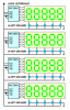
If your 5 inch displays are common cathode then you can use high current MIC5891 serial-to-parallel "sourcing" drivers which have a "VBB" pin specifically for displays with multiple LEDs per segment that need higher voltage drive. With my MacMux designs you would need 6 pins (you would only need three of the four 5-digit display modules in the drawing below). Advantages are full-brightness display with PWM brightness control. A relatively high refresh rate and 20% duty cycle per digit.
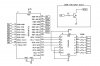
I've built a DCF77 Clock with 6 Digits 10cm 7Segement Displays with common Anode.
As Driver for the segments I've used an ULN 2003.
To drive the Anodes of the Digits there is a P-Channel Mos Fet, driven By an N-Channel Mos Fet ( BS 170 ).
Thats needed by using 12V for the Display Voltage.
The Controller works only with 5V.
Alternative it could be possible to use as Anode driver one from the UDN... Series.
To generate the Characters there is a Look Up Table into the Controller.
At Place 0 are the activated Digigts for "0".
At Place 1 are the digits for "1" and so on.
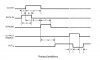
The Multiplexing of the Anodes is done in an Timer Interrupt Routine.
So all the Digits have the same Brigtness.
The Multiplexing goes from right to left. The opposite Direction is possible also of course.
// Timer 0 overflow interrupt service routine
interrupt [TIM0_OVF] void timer0_ovf_isr(void)
{
#asm("SEI");      /* Interrupts für Stoppuhr freigeben !*/
switch (uc_segmentcounter)
    {
    case 0:
    PORTC=0;
    PORTA.5=0;
    delay_us(20);
    PORTA.0=1;
    PORTC=uc_segment[uc_segmentcounter];
    if(PINB.2>0)
        {
        PORTC.7=1;
        };
    break;
    case 1:
    PORTC=0;
    PORTA.0=0;
    delay_us(20);
    PORTA.1=1;
    PORTC=uc_segment[uc_segmentcounter];
    break;
    case 2:
    PORTC=0;
    PORTA.1=0;
    delay_us(20);
    PORTA.2=1;
    PORTC=uc_segment[uc_segmentcounter];
    break;
    case 3:
    PORTC=0;
    PORTA.2=0;
    delay_us(20);
    PORTA.3=1;
    PORTC=uc_segment[uc_segmentcounter];
    break;
    case 4:
    PORTC=0;
    PORTA.3=0;
    delay_us(20);
    PORTA.4=1;
    PORTC=uc_segment[uc_segmentcounter];
    break;
    case 5:
    PORTC=0;
    PORTA.4=0;
    delay_us(20);
    PORTA.5=1;
    PORTC=uc_segment[uc_segmentcounter];
    break;

    };
uc_segmentcounter++;
if(uc_segmentcounter>5){uc_segmentcounter=0;};
}
The Variable Segmentcounter points the actual Digit.
When all Digits are processed it starts again.
At the variable array uc_segment ist stored the actual active segments for each digit.
The Timer Overflow Routine should be called minimum each 2ms for 6 Digits to avoid flicker.
The Code is written with CodeVision AVR in "C" for an ATMEGA16 Controller.
The princip should work in an PIC Controller also.
I am most interested in Mike's suggestion using the MIC5891 chip. This should work with both the small and large digits right?
This is my understanding:
Supply a constant clock
Shift one pin high and low for data
Shift Output Enable high at the end of data
Scan through the sets of displays using a Timer Interrupt
Refresh the values
Yes. On regular displays you would connect the VBB pin on the MIC5891's to the 5v VDD pin and on the large multi-led-per-segment displays you would connect VBB to whatever high voltage you needed.
The wiring is similar to that in the drawing below. There are five column/digit driver lines and one PWM line. The <dat> pin on each driver IC is also connected to a unique column/digit line and the <clk> pin on each driver IC is connected in parallel and connected to the remaining column/digit line. The <lat> and </oe> pins are all connected together and driven by the PIC PWM pin. The PWM signal provides complete fade-to-black brightness control and allows re-tasking the five column/digit driver lines for temporary use as <clk> and <dat> lines to load the shift registers in parallel while PWM is high (display "off") at the beginning of each column/digit update interval (by writing 8 bytes and clocks onto the column/digit driver buss in about 24 cycles).
I'll try to come up with a better drawing for you as time permits.
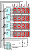
That circuit is for common anode displays. You could use a single PNP or P-FET "source" driver on each column for small displays (5v) or you could use an NPN+PNP or N-FET+P-FET "source" driver pair on each column for the larger multi-led-per-segment displays (>5v)...
This site uses cookies to help personalise content, tailor your experience and to keep you logged in if you register.
By continuing to use this site, you are consenting to our use of cookies.